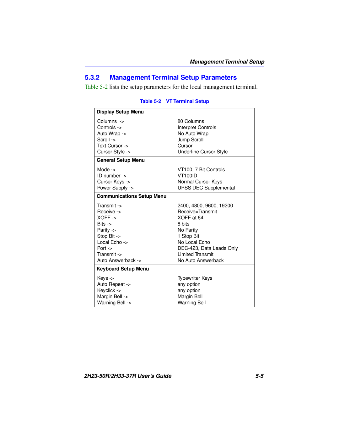
Management Terminal Setup
5.3.2Management Terminal Setup Parameters
Table
Table | |
|
|
Display Setup Menu |
|
Columns | 80 Columns |
Controls | Interpret Controls |
Auto Wrap | No Auto Wrap |
Scroll | Jump Scroll |
Text Cursor | Cursor |
Cursor Style | Underline Cursor Style |
|
|
General Setup Menu |
|
Mode | VT100, 7 Bit Controls |
ID number | VT100ID |
Cursor Keys | Normal Cursor Keys |
Power Supply | UPSS DEC Supplemental |
|
|
Communications Setup Menu |
|
Transmit | 2400, 4800, 9600, 19200 |
Receive | Receive=Transmit |
XOFF | XOFF at 64 |
Bits | 8 bits |
Parity | No Parity |
Stop Bit | 1 Stop Bit |
Local Echo | No Local Echo |
Port | |
Transmit | Limited Transmit |
Auto Answerback | No Auto Answerback |
|
|
Keyboard Setup Menu |
|
Keys | Typewriter Keys |
Auto Repeat | any option |
Keyclick | any option |
Margin Bell | Margin Bell |
Warning Bell | Warning Bell |
|
|
|