DLE22-MA, DLE32-MA
Page
Revision/Update Information
United States Government Restricted Rights
Achtung
Cabletron SYSTEMS, INC. Program License Agreement
Page
Declaration of Conformity
Contents
Viii DLE22-MA, DLE32-MA, DLE23-MA and DLE33-MA User’s Guide
Contents
11.1
20.1
Appendix B DELTX-UI,DELFX-UI and DELF3-UI Specifications
Page
DLE22-MA, DLE32-MA, DLE23-MA, and DLE33-MA User’s Guide
Using this Guide
Intended Audience
Structure of this Guide
Xiv DLE22-MA, DLE32-MA, DLE23-MA, and DLE33-MA User’s Guide
Document Conventions
World Wide Web
Related Documentation
Correspondence
Documentation Comments
Xvi DLE22-MA, DLE32-MA, DLE23-MA, and DLE33-MA User’s Guide
Getting Help
Overview
Safety
Xviii DLE22-MA, DLE32-MA, DLE23-MA and DLE33-MA User’s Guide
Safety Requirements
Safety Requirements
Xx DLE22-MA, DLE32-MA, DLE23-MA and DLE33-MA User’s Guide
DLM6C-AA
Xxii DLE22-MA, DLE32-MA, DLE23-MA and DLE33-MA User’s Guide
Un número impar de diagonales de
Xxiv DLE22-MA, DLE32-MA, DLE23-MA and DLE33-MA User’s Guide
Bevor Sie die Einstellungen des COM-Ports
Xxvi DLE22-MA, DLE32-MA, DLE23-MA and DLE33-MA User’s Guide
Changes no SE HA Guardado
Lorsque le port COM est configuré pour une
If the DLE2X-MA and DLE3X-MA are being
Xxx DLE22-MA, DLE32-MA, DLE23-MA and DLE33-MA User’s Guide
Al instalar un módulo DELFX-UI o DELF3-UI
Page
DLE2X-MA and DLE3X-MA Overview
Chapter Introduction
Introduction
DLE2X-MA and DLE3X-MA Overview
Full Duplex Switched Ethernet
Connectivity
SmartTrunk
Standards Compatibility
Switching Options
Lanview Diagnostic LEDs
Management
Local Management Features
Year 2000 Compliant
Runtime IP Address Discovery
Description Application
Optional Features
Chapter Network Requirements
10BASE-T Network
100BASE-TX Network
100BASE-FX Fiber Optic Network
Unpacking the DLE2X-MA and DLE3X-MA
Required Tools
DLE2X-MA and DLE3X-MA Options
DLE22-MA, DLE32-MA, DLE23-MA and DLE33-MA User’s Guide
Installing an Interface Module
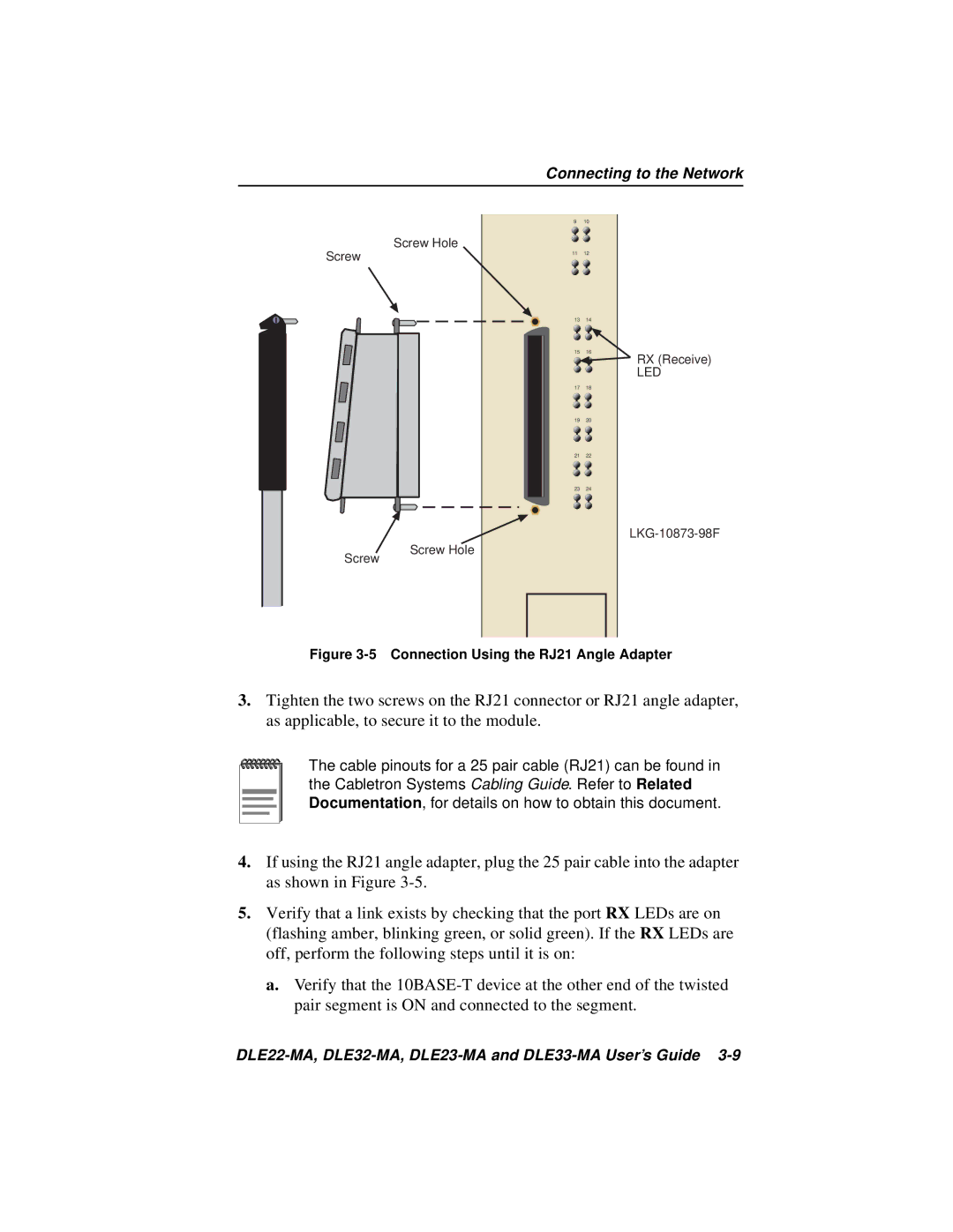
Connecting to the Network
Connecting to the Network
DLE22-MA and DLE32-MA Twisted Pair Connection
Cable Pinouts RJ45 Crossover Cable
DLE33-MA and DLE23-MA Twisted Pair Connection
Connection Using the RJ21 Angle Adapter
Connecting a Twisted Pair Segment to
DELTX-UI
10 DLE22-MA, DLE32-MA, DLE23-MA and DLE33-MA User’s Guide
DELTX-UI Crossover Switch
12 DLE22-MA, DLE32-MA, DLE23-MA and DLE33-MA User’s Guide
Port RX LED flashes green and amber during bootup
14 DLE22-MA, DLE32-MA, DLE23-MA and DLE33-MA User’s Guide
Completing the Installation
Using Lanview
Chapter Troubleshooting
Troubleshooting
LED
Using Lanview
DELTX-UI LED
DELTX-UI LED
Troubleshooting Checklist
Using the Reset Button
Using the Reset Button
Page
DLE22-MA,DLE32-MA,DLE23-MA and DLE33-MA User’s Guide
Chapter Local Management
Key Function
Local Management Keyboard Conventions
Management Terminal Setup
Management Terminal Setup
Console Cable Connection
Management Terminal Connection
Uninterruptible Power Supply UPS
Display Setup Menu
Management Terminal Setup Parameters
Accessing Local Management
Accessing Local Management
Telnet Connections
Local Management Password Screen
Navigating Local Management Screens
Hsim
10 DLE22-MA,DLE32-MA,DLE23-MA and DLE33-MA User’s Guide
Exiting Local Management Screens
Selecting Local Management Menu Screen Items
12 DLE22-MA,DLE32-MA,DLE23-MA and DLE33-MA User’s Guide
Main Menu Screen
Chassis Menu Screen
Chassis Menu Screen
14 DLE22-MA,DLE32-MA,DLE23-MA and DLE33-MA User’s Guide
Chassis Configuration Screen
000.000.000.000
Chassis Configuration Screen
16 DLE22-MA,DLE32-MA,DLE23-MA and DLE33-MA User’s Guide
Subnet Mask Modifiable
Setting the IP Address
Setting the Subnet Mask
Setting the Chassis Date
18 DLE22-MA,DLE32-MA,DLE23-MA and DLE33-MA User’s Guide
Setting the Chassis Time
Setting the Screen Lockout Time
Entering a New Screen Refresh Time
20 DLE22-MA,DLE32-MA,DLE23-MA and DLE33-MA User’s Guide
Operational Mode Warning Screen
Setting the Operational Mode
22 DLE22-MA,DLE32-MA,DLE23-MA and DLE33-MA User’s Guide
Snmp Community Names Screen
10 Snmp Community Names Screen
Snmp Community Names Screen
24 DLE22-MA,DLE32-MA,DLE23-MA and DLE33-MA User’s Guide
Establishing Community Names
Snmp Traps Screen
Snmp Traps Screen
Configuring the Trap Table
Chassis Environmental Screen
26 DLE22-MA,DLE32-MA,DLE23-MA and DLE33-MA User’s Guide
12 Chassis Environmental Information Screen
Chassis Environmental Screen
28 DLE22-MA,DLE32-MA,DLE23-MA and DLE33-MA User’s Guide
Port Redirect Function Screen
13 Port Redirect Function Screen
Port Redirect Function Screen
Displaying the Source and Destination Entries
Changing Source and Destination Ports
30 DLE22-MA,DLE32-MA,DLE23-MA and DLE33-MA User’s Guide
Module Selection Screen
Module Selection Screen
14 Module Selection Screen
32 DLE22-MA,DLE32-MA,DLE23-MA and DLE33-MA User’s Guide
Selecting a Module
Module Menu Screen
Module Menu Screen
15 Module Menu Screen
34 DLE22-MA,DLE32-MA,DLE23-MA and DLE33-MA User’s Guide
Module Configuration Menu Screen
Module Configuration Menu Screen
36 DLE22-MA,DLE32-MA,DLE23-MA and DLE33-MA User’s Guide
General Configuration Screen
General Configuration Screen
38 DLE22-MA,DLE32-MA,DLE23-MA and DLE33-MA User’s Guide
Displays the total time that the module has been operating
40 DLE22-MA,DLE32-MA,DLE23-MA and DLE33-MA User’s Guide
To set the IP address, perform the following steps
Are YOU Sure YOU Want to CONTINUE? Yesno
42 DLE22-MA,DLE32-MA,DLE23-MA and DLE33-MA User’s Guide
Setting the Default Gateway
Setting the Module Date
Setting the Tftp Gateway IP Address
44 DLE22-MA,DLE32-MA,DLE23-MA and DLE33-MA User’s Guide
Setting the Module Time
Entering a New Screen Refresh Time
46 DLE22-MA,DLE32-MA,DLE23-MA and DLE33-MA User’s Guide
Setting the Management Mode
Configuring the COM Port
19 COM Port Warning Screen
48 DLE22-MA,DLE32-MA,DLE23-MA and DLE33-MA User’s Guide
Changing the Com Port Application
50 DLE22-MA,DLE32-MA,DLE23-MA and DLE33-MA User’s Guide
Clearing Nvram
Enabling/Disabling IP Fragmentation
21 Snmp Community Names Screen
52 DLE22-MA,DLE32-MA,DLE23-MA and DLE33-MA User’s Guide
Establishing Community Names
22 Snmp Traps Screen
54 DLE22-MA,DLE32-MA,DLE23-MA and DLE33-MA User’s Guide
Switch Configuration Screen
Switch Configuration Screen
56 DLE22-MA,DLE32-MA,DLE23-MA and DLE33-MA User’s Guide
Displays the base MAC address of the switch
58 DLE22-MA,DLE32-MA,DLE23-MA and DLE33-MA User’s Guide
Setting the STA
Setting Enabling or Disabling the Port Status
Setting the Age Time
60 DLE22-MA,DLE32-MA,DLE23-MA and DLE33-MA User’s Guide
Ethernet Full Duplex Configuration Screen
Ethernet Full Duplex Configuration Screen
62 DLE22-MA,DLE32-MA,DLE23-MA and DLE33-MA User’s Guide
Setting the Operation Mode
SmartTrunk and the Configuration Screen
SmartTrunk Configuration Rules
SmartTrunk and the Configuration Screen
64 DLE22-MA,DLE32-MA,DLE23-MA and DLE33-MA User’s Guide
SmartTrunk Configuration Screen
Port #
66 DLE22-MA,DLE32-MA,DLE23-MA and DLE33-MA User’s Guide
Enabling the Connection
Module Specific Configuration Menu Screen
Module Specific Configuration Menu Screen
Displaying the SmartTrunk Ports
68 DLE22-MA,DLE32-MA,DLE23-MA and DLE33-MA User’s Guide
26 Module Specific Configuration Menu Screen
Flash Download
70 DLE22-MA,DLE32-MA,DLE23-MA and DLE33-MA User’s Guide
System Resources Screen
System Resources Screen
Setting the Reset Peak Utilization
72 DLE22-MA,DLE32-MA,DLE23-MA and DLE33-MA User’s Guide
High Speed Interface Configuration Menu Screen DLE2X-MA only
High Speed Interface Configuration Menu Screen DLE2X-MA Only
74 DLE22-MA,DLE32-MA,DLE23-MA and DLE33-MA User’s Guide
Setting the DELTX-UI Operational Mode
Configuring an DELFX-UI or DELF3-UI in Port 25 or
Setting the DELFX-UI and DELF3-UI Operational Mode
Configuring an DELTX-UI in Port 25 or
76 DLE22-MA,DLE32-MA,DLE23-MA and DLE33-MA User’s Guide
Setting the DELTX-UI Advertised Ability
Flash Download Screen
Flash Download Screen
29 Flash Download Screen
78 DLE22-MA,DLE32-MA,DLE23-MA and DLE33-MA User’s Guide
Tftp Gateway IP Addr Selectable
80 DLE22-MA,DLE32-MA,DLE23-MA and DLE33-MA User’s Guide
Image File Download Using Tftp
Image File Download Using Runtime
82 DLE22-MA,DLE32-MA,DLE23-MA and DLE33-MA User’s Guide
Image File Download Using BootP
Shows which ports are currently set as source ports
84 DLE22-MA,DLE32-MA,DLE23-MA and DLE33-MA User’s Guide
Port Redirect Function Screen
86 DLE22-MA,DLE32-MA,DLE23-MA and DLE33-MA User’s Guide
Broadcast Suppression Screen
Broadcast Suppression Screen
Setting the Threshold
Setting the Reset Peak Switch
Module Statistics Menu Screen
88 DLE22-MA,DLE32-MA,DLE23-MA and DLE33-MA User’s Guide
Switch Statistics Screen
Switch Statistics Screen
90 DLE22-MA,DLE32-MA,DLE23-MA and DLE33-MA User’s Guide
Displays the number of frames filtered by the interface
Using the Clear Counters Command
Interface Statistics Screen
Interface Statistics Screen
MTU
92 DLE22-MA,DLE32-MA,DLE23-MA and DLE33-MA User’s Guide
InNonUnicast Read-only
94 DLE22-MA,DLE32-MA,DLE23-MA and DLE33-MA User’s Guide
Displaying Interface Statistics
Rmon Statistics Screen
Rmon Statistics Screen
MS 700 Local Management Rmon
96 DLE22-MA,DLE32-MA,DLE23-MA and DLE33-MA User’s Guide
Rmon Index Read-only
98 DLE22-MA,DLE32-MA,DLE23-MA and DLE33-MA User’s Guide
Total Octets Read-only
100 DLE22-MA,DLE32-MA,DLE23-MA and DLE33-MA User’s Guide
Displaying Rmon Statistics
Network Tools
Network Tools
102 DLE22-MA,DLE32-MA,DLE23-MA and DLE33-MA User’s Guide
Built-in Commands
Views cache data
104 DLE22-MA,DLE32-MA,DLE23-MA and DLE33-MA User’s Guide
Bridge ENABLE/DISABLE IFNUM/ALL
106 DLE22-MA,DLE32-MA,DLE23-MA and DLE33-MA User’s Guide
Netstat option
108 DLE22-MA,DLE32-MA,DLE23-MA and DLE33-MA User’s Guide
Syntaxreset
110 DLE22-MA,DLE32-MA,DLE23-MA and DLE33-MA User’s Guide
Traceroute IP address
112 DLE22-MA,DLE32-MA,DLE23-MA and DLE33-MA User’s Guide
Telnet IP address Port #
114 DLE22-MA,DLE32-MA,DLE23-MA and DLE33-MA User’s Guide
Linktrap
Atmstpstate State
116 DLE22-MA,DLE32-MA,DLE23-MA and DLE33-MA User’s Guide
Special Commands
DLE22-MA, DLE32-MA, DLE23-MA and DLE33-MA User’s Guide A-1
Device Specifications
Physical Properties
Environmental Requirements
DELF3-UI
INPUT/OUTPUT Ports
DLE22-MA, DLE32-MA, DLE23-MA and DLE33-MA User’s Guide A-3
COM Port Pinout Assignments
Regulatory Compliance
COM Port Pinout Assignments
Page
DLE28-MA, DLE38-MA, DLE29-MA and DLE39-MA User’s Guide B-1
Appendix B DELTX-UI, DELFX-UI and DELF3-UI Specifications
DLE28-MA, DLE38-MA, DLE29-MA and DLE39-MA User’s Guide
DELFX-UI
DLE28-MA, DLE38-MA, DLE29-MA and DLE39-MA User’s Guide B-3
DELF3-UI
Page
DLE22-MA, DLE32-MA, DLE23-MA and DLE33-MA User’s Guide C-1
Setting the Mode Switch
Dram Mode Switch Bank
DLE22-MA, DLE32-MA, DLE23-MA and DLE33-MA User’s Guide C-3
Setting the Mode Switch
Figure C-2 Fast Ethernet Interface Module Connector Location
Installing Optional Fast Ethernet Interface Modules
DLE22-MA, DLE32-MA, DLE23-MA and DLE33-MA User’s Guide C-5
Installing Optional Fast Ethernet Interface Modules
Remove the screw from the rear standoff. Save the screw
DLE22-MA, DLE32-MA, DLE23-MA and DLE33-MA User’s Guide C-7
Figure C-4 Installing the Fast Ethernet Interface Module
Page
DLE22-MA, DLE32-MA, DLE23-MA, DLE33-MA User’s Guide Index-1
Numerics
Index-2 DLE22-MA, DLE32-MA, DLE23-MA, DLE33-MA User’s Guide
Index
DLE22-MA, DLE32-MA, DLE23-MA, DLE33-MA User’s Guide Index-3
Index-4 DLE22-MA, DLE32-MA, DLE23-MA, DLE33-MA User’s Guide
Page
9032627