Chapter 5: Local Management
Event Message Line
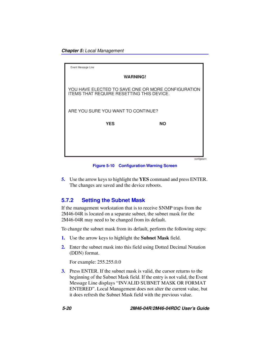
WARNING!
YOU HAVE ELECTED TO SAVE ONE OR MORE CONFIGURATION ITEMS THAT REQUIRE RESETTING THIS DEVICE.
ARE YOU SURE YOU WANT TO CONTINUE?
YES | NO |
confgwarn
Figure 5-10 Configuration Warning Screen
5.Use the arrow keys to highlight the YES command and press ENTER. The changes are saved and the device reboots.
5.7.2Setting the Subnet Mask
If the management workstation that is to receive SNMP traps from the
To change the subnet mask from its default, perform the following steps:
1.Use the arrow keys to highlight the Subnet Mask field.
2.Enter the subnet mask into this field using Dotted Decimal Notation (DDN) format.
For example: 255.255.0.0
3.Press ENTER. If the subnet mask is valid, the cursor returns to the beginning of the Subnet Mask field. If the entry is not valid, the Event Message Line displays “INVALID SUBNET MASK OR FORMAT ENTERED”. Local Management does not alter the current value, but it does refresh the Subnet Mask field with the previous value.
|