Chapter 5: Local Management
5.10SWITCH CONFIGURATION SCREEN
NOTE |
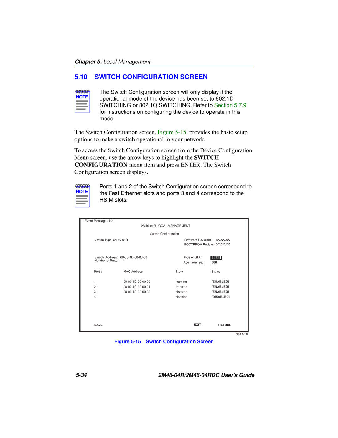
The Switch Configuration screen will only display if the operational mode of the device has been set to 802.1D SWITCHING or 802.1Q SWITCHING. Refer to Section 5.7.9 for instructions on configuring the device to operate in this mode.
The Switch Configuration screen, Figure
To access the Switch Configuration screen from the Device Configuration Menu screen, use the arrow keys to highlight the SWITCH CONFIGURATION menu item and press ENTER. The Switch Configuration screen displays.
NOTE |
Ports 1 and 2 of the Switch Configuration screen correspond to the Fast Ethernet slots and ports 3 and 4 correspond to the HSIM slots.
Event Message Line
|
|
|
| |
| Switch Configuration |
|
| |
Device Type: | Firmware Revision: | XX.XX.XX | ||
|
| BOOTPROM Revision: XX.XX.XX | ||
Switch Address: | Type of STA: |
|
| |
[IEEE] |
| |||
Number of Ports: | 4 | Age Time (sec): | 300 |
|
|
|
| ||
Port # | MAC Address | State | Status | |
1 | learning | [ENABLED] | ||
2 | listening | [ENABLED] | ||
3 | blocking | [ENABLED] | ||
4 |
| disabled | [DISABLED] | |
SAVE |
| EXIT | RETURN | |
Figure 5-15 Switch Configuration Screen
|