APPENDIX B
FE-100TX, FE-100FX, AND FE-100F3
SPECIFICATIONS
The 2M46-04R supports three Fast Ethernet Interface Modules:
•FE-100TX (Section B.1)
•FE-100FX (Section B.2)
•FE-100F3 (Section B.3)
This appendix provides the specifications for these modules.
B.1 FE-100TX
The FE-100TX uses an RJ45 connector supporting Category 5 Unshielded Twisted Pair (UTP) cabling with an impedance between 85 and 111 ohms.
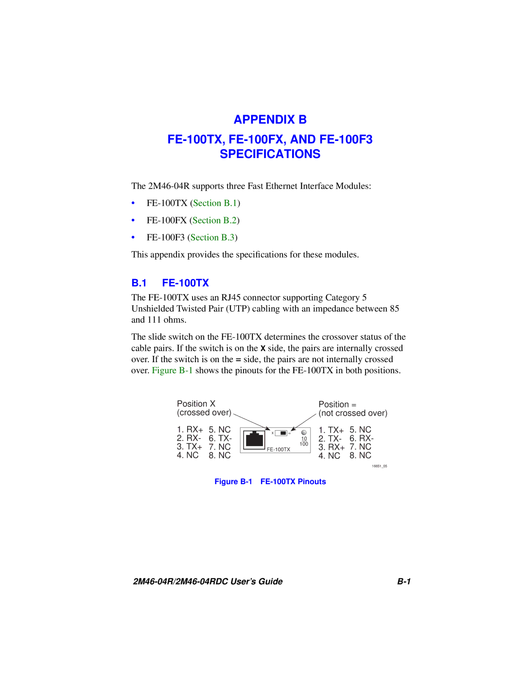
The slide switch on the FE-100TX determines the crossover status of the cable pairs. If the switch is on the X side, the pairs are internally crossed over. If the switch is on the = side, the pairs are not internally crossed over. Figure B-1shows the pinouts for the FE-100TX in both positions.
Position X (crossed over)
1.RX+ 5. NC
2.RX- 6. TX-
3.TX+ 7. NC
4.NC 8. NC
Position =
(not crossed over)
1.TX+ 5. NC
2.TX- 6. RX-
3.RX+ 7. NC
4.NC 8. NC
16651_05
Figure B-1 FE-100TX Pinouts
2M46-04R/2M46-04RDC User’s Guide | B-1 |