Appendix C: Optional Installations and Mode Switch Bank Settings
Coverplate
HSIM 1
1
Rear
Standoff
![]()
![]()
![]() Front
Front
![]() Standoffs
Standoffs
2
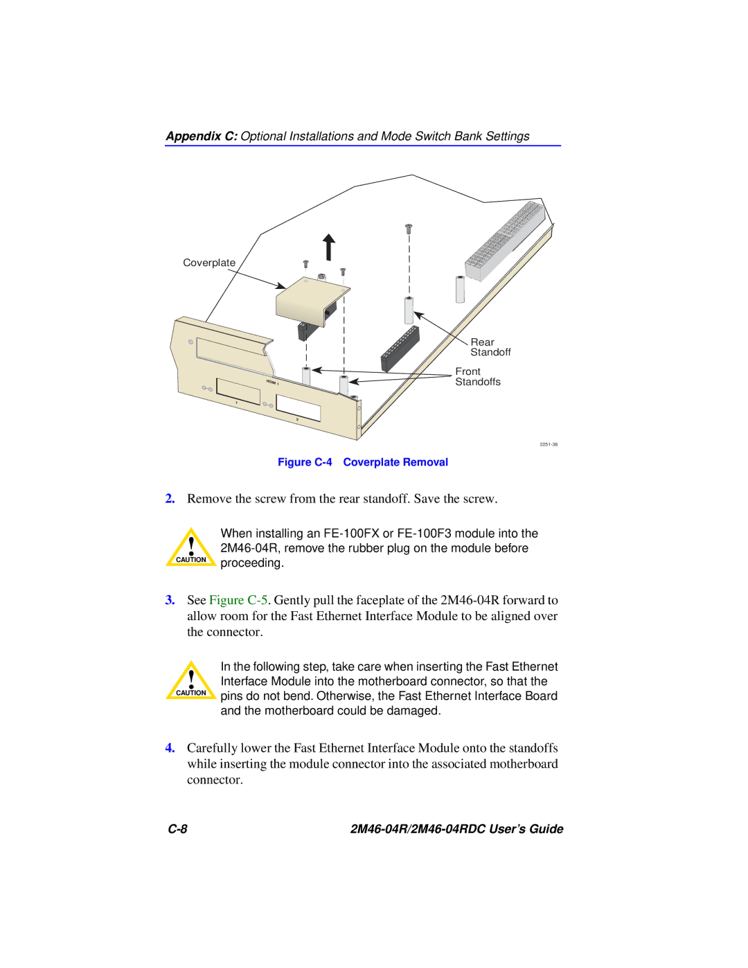
Figure C-4 Coverplate Removal
2.Remove the screw from the rear standoff. Save the screw.
When installing an
!
3.See Figure
In the following step, take care when inserting the Fast Ethernet
!Interface Module into the motherboard connector, so that the
CAUTION | pins do not bend. Otherwise, the Fast Ethernet Interface Board |
| |
| and the motherboard could be damaged. |
4.Carefully lower the Fast Ethernet Interface Module onto the standoffs while inserting the module connector into the associated motherboard connector.
|