Delta DOP Series HMI Connection ManualDOP-A/AE/AS Series
Danfoss VLT 2800 (FC Protocol) | Back to Table |
A. HMI factory setting
Baud rate: 9600, 8, Even, 1,
PLC station number: 1.
Control area/status area: None / None.
![]()
![]()
![]()
![]() NOTE
NOTE
1)Delta HMI can be connected to for
2)Each data length format of Danfoss AC drive parameter is not fixed, therefore, “Multiple Duplicate” function is not provided.
3)Max. supported alarm number is 16. If the alarm number is over 16, a fault will occur.
4)Does not support “optimum read/write” characteristic.
5)If the selected element is a string, the minimum data length should be more than 2.
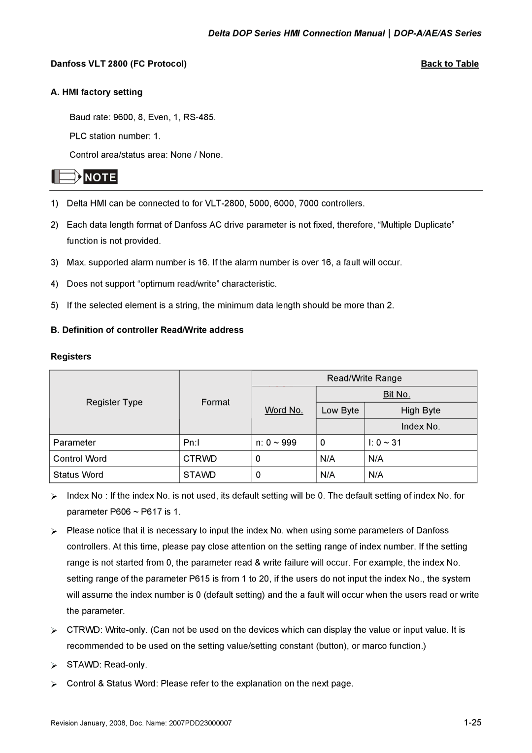
B. Definition of controller Read/Write address
Registers
|
|
| Read/Write Range | ||
Register Type | Format | Word No. |
|
| Bit No. |
Low Byte |
| High Byte | |||
|
|
| |||
|
|
|
|
| Index No. |
Parameter | Pn:I | n: 0 ~ 999 | 0 |
| I: 0 ~ 31 |
|
|
|
|
|
|
Control Word | CTRWD | 0 | N/A |
| N/A |
|
|
|
|
|
|
Status Word | STAWD | 0 | N/A |
| N/A |
|
|
|
|
|
|
¾Index No : If the index No. is not used, its default setting will be 0. The default setting of index No. for parameter P606 ~ P617 is 1.
¾Please notice that it is necessary to input the index No. when using some parameters of Danfoss controllers. At this time, please pay close attention on the setting range of index number. If the setting range is not started from 0, the parameter read & write failure will occur. For example, the index No. setting range of the parameter P615 is from 1 to 20, if the users do not input the index No., the system will assume the index number is 0 (default setting) and the a fault will occur when the users read or write the parameter.
¾CTRWD:
¾STAWD:
¾Control & Status Word: Please refer to the explanation on the next page.
Revision January, 2008, Doc. Name: 2007PDD23000007 |
