Delta DOP Series HMI Connection ManualDOP-A/AE/AS Series
Omron CJ1/CS1 Series PLC | Back to Table |
A. HMI factory settings
Baud rate: 9600, 7, EVEN, 2.
Controller station number: 0.
Control area/status area: D0 / D10.
¾This driver can support OMRON CS/CJ/CP1/CQM/CV/CVM series PLC simultaneously.
![]()
![]()
![]()
![]() NOTE
NOTE
The meaning of Communication Error Message:
1)Word Device:
The Device Name and Address Value will display. For example, if using CIO, H, A, D, E, T, C, W, EM, IR, DR, TK, it will show CIOn, Hn, An, Dn, Em.n, Tn, Cn, Wn, EMn, IRn, DRn, TKn respectively. “n” is the Address Value.
2)Bit Device:
The Device Name and Word Address Value will display, but the Bit Address Value will not. For example, if using CIO, H, A, D, E, T, C, W, EM, IR, DR, TK, it will show CIOBn, HBn, ABn, DBn, EBm.n, TBn, CBn, WBn, EMBn, IRBn, DRBn, TKBn respectively. “n” is the Word Address Value.
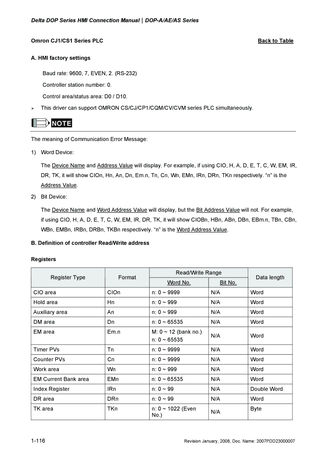
B. Definition of controller Read/Write address
Registers
Register Type | Format | Read/Write Range | Data length |
| |
Word No. | Bit No. |
| |||
|
|
|
| ||
CIO area | CIOn | n: 0 ~ 9999 | N/A | Word |
|
|
|
|
|
|
|
Hold area | Hn | n: 0 ~ 999 | N/A | Word |
|
|
|
|
|
|
|
Auxiliary area | An | n: 0 ~ 999 | N/A | Word |
|
|
|
|
|
|
|
DM area | Dn | n: 0 ~ 65535 | N/A | Word |
|
|
|
|
|
|
|
EM area | Em.n | M: 0 ~ 12 (bank no.) | N/A | Word |
|
|
| n: 0 ~ 65535 |
| ||
|
|
|
|
| |
|
|
|
|
|
|
Timer PVs | Tn | n: 0 ~ 9999 | N/A | Word |
|
|
|
|
|
|
|
Counter PVs | Cn | n: 0 ~ 9999 | N/A | Word |
|
|
|
|
|
|
|
Work area | Wn | n: 0 ~ 999 | N/A | Word |
|
|
|
|
|
|
|
EM Current Bank area | EMn | n: 0 ~ 65535 | N/A | Word |
|
|
|
|
|
|
|
Index Register | IRn | n: 0 ~ 99 | N/A | Double Word |
|
|
|
|
|
|
|
DR area | DRn | n: 0 ~ 99 | N/A | Word |
|
|
|
|
|
|
|
TK area | TKn | n: 0 ~ 1022 (Even | N/A | Byte |
|
|
| No.) |
|
| |
|
|
|
|
| |
|
|
|
|
|
|
| Revision January, 2008, Doc. Name: 2007PDD23000007 | ||||
