Delta DOP Series HMI Connection ManualDOP-A/AE/AS Series
slot 0: X48
slot 1: Y32
slot 2: empty16
Analog Type
slot 3: X4W
slot 4: Y4W
3)Communication Protocol: External I/O (X, Y, WX, WY)
yAddress rules:[r][u][s][n/b].
i)Word no/Bit no [n/b]
ii)Slot number [s]
iii)Unit number [u]
iv)Remote number [r]
Only support
v)ex1: WX103 represents unit 1, word 3 of slot 0
vi)ex2: X103 represents bit 3 of slot 1
vii)ex3: X113 represents bit 13 of slot 1
viii)ex4: Y2004 represents unit 2, bit 4 of slot 0
ix)ex5: Y2104 represents unit 2, bit 4 of slot 1
yExternal I/O (X, Y, WX, WY) cannot read and write several addresses one time so they do not support “optimum read/write” characteristic.
Internal Output
yShared Internal Output (M, WM) read and write the same address. For example,
i)M3ab and WM3a: the read and write address of M3ab is the bit b of WM3a.
yCPU Link Area (L, WL) are the same as Shared Internal Output (M, WM). CPU Link Area (L, WL) also read and write the same address.
i)Only support
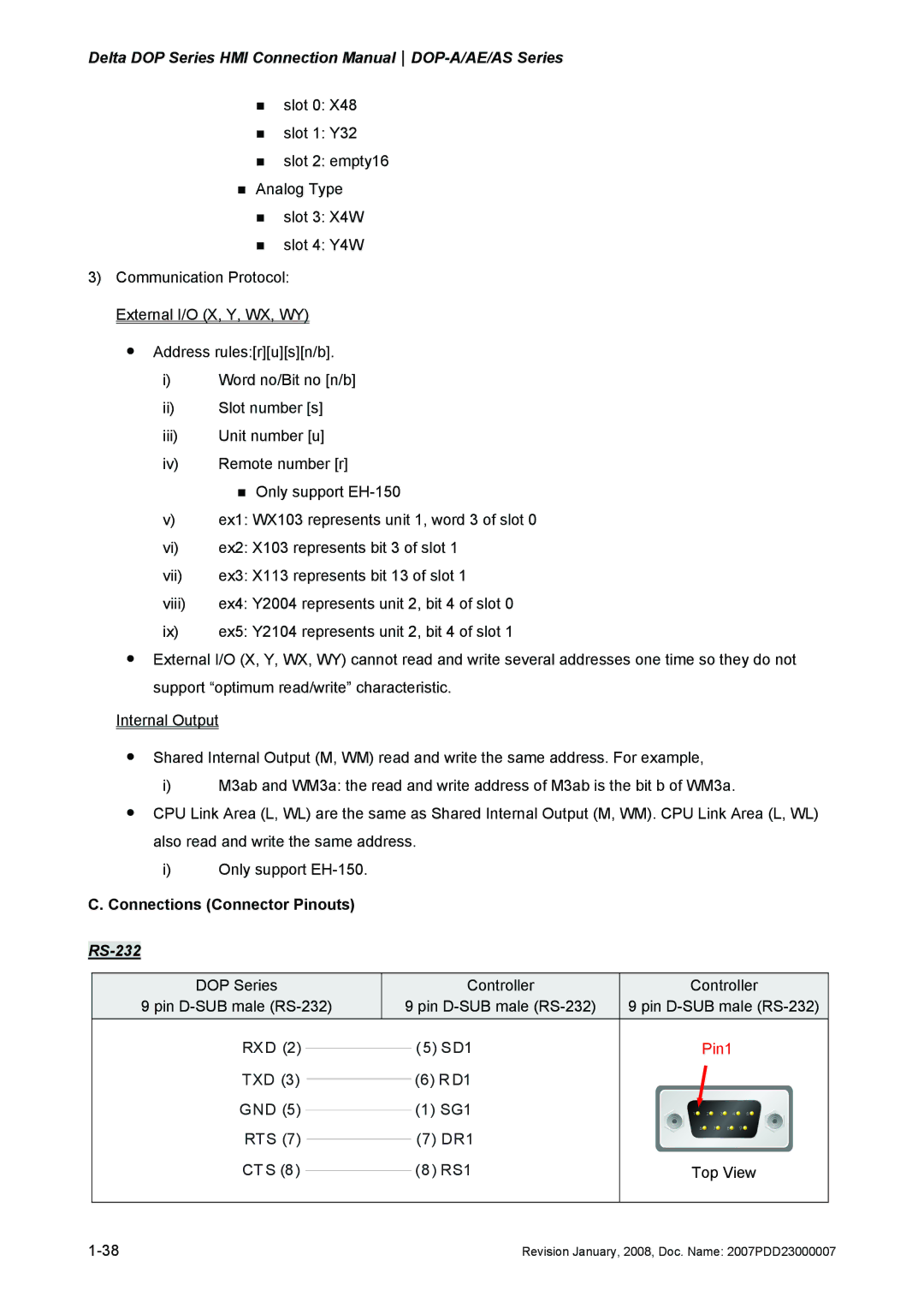
C. Connections (Connector Pinouts)
RS-232
DOP Series |
| Controller | Controller | ||
9 pin | 9 pin | 9 pin | |||
RXD (2) |
|
|
| (5) SD1 | Pin1 |
|
|
| |||
TXD (3) |
|
| (6) RD1 |
| |
|
|
| |||
GND (5) |
|
| (1) SG1 |
| |
|
|
| |||
RTS (7) |
|
| (7) DR1 |
| |
|
|
| |||
CT S (8) |
|
| (8 ) RS1 | Top View | |
|
| ||||
|
|
|
|
|
|
Revision January, 2008, Doc. Name: 2007PDD23000007 |