Read/write function block data
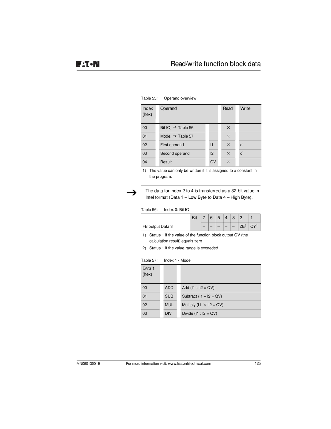
Table 55: | Operand overview |
|
|
|
|
|
| |
|
|
|
|
|
|
|
|
|
Index |
| Operand |
|
|
| Read |
| Write |
(hex) |
|
|
|
|
|
|
|
|
|
|
|
|
|
|
|
|
|
00 |
| Bit IO, J Table 56 |
|
|
| × |
|
|
01 |
| Mode, J Table 57 |
|
|
| × |
|
|
02 |
| First operand |
| I1 |
| × |
| c1 |
03 |
| Second operand |
| I2 |
| × |
| c1 |
04 |
| Result |
| QV |
| × |
|
|
|
|
|
|
|
|
|
|
|
1)The value can only be written if it is assigned to a constant in the program.
J
The data for index 2 to 4 is transferred as a
Table 56: Index 0: Bit IO
| Bit | 7 | 6 | 5 | 4 | 3 | 2 | 1 |
FB output Data 3 |
| – | – | – | – | – | ZE1 | CY1 |
1)Status 1 if the value of the function block output QV (the calculation result) equals zero
2)Status 1 if the value range is exceeded
Table 57: |
| Index 1 - Mode | ||
|
|
|
|
|
Data 1 |
|
|
|
|
(hex) |
|
|
|
|
|
|
|
|
|
00 |
| ADD |
| Add (I1 + I2 = QV) |
01 |
| SUB |
| Subtract (I1 – I2 = QV) |
|
|
|
|
|
02 |
| MUL |
| Multiply (I1 × I2 = QV) |
|
|
|
|
|
03 |
| DIV |
| Divide (I1 : I2 = QV) |
|
|
|
|
|
MN05013001E | For more information visit: www.EatonElectrical.com | 125 |