Read/write function block data
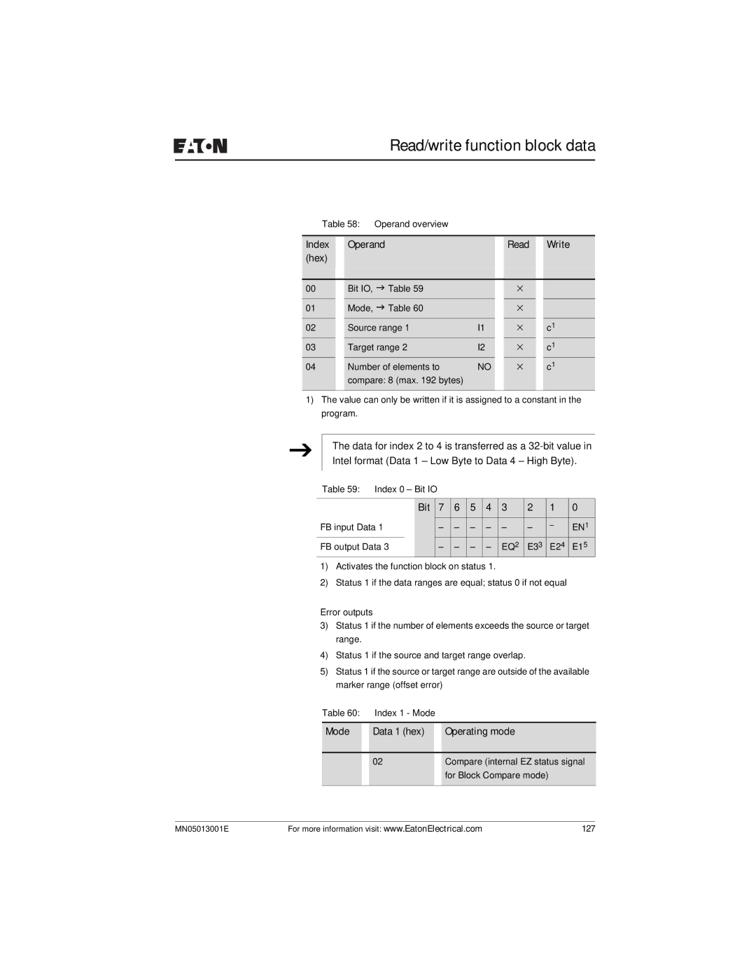
Table 58: Operand overview
Index |
| Operand |
|
| Read |
| Write |
(hex) |
|
|
|
|
|
|
|
|
|
|
|
|
|
|
|
00 |
| Bit IO, J Table 59 |
|
| × |
|
|
01 |
| Mode, J Table 60 |
|
| × |
|
|
|
|
|
|
|
|
|
|
02 |
| Source range 1 | I1 |
| × |
| c1 |
03 |
| Target range 2 | I2 |
| × |
| c1 |
04 |
| Number of elements to | NO |
| × |
| c1 |
|
| compare: 8 (max. 192 bytes) |
|
|
|
|
|
|
|
|
|
|
|
|
|
1)The value can only be written if it is assigned to a constant in the program.
J
The data for index 2 to 4 is transferred as a
Table 59: Index 0 – Bit IO
| Bit | 7 | 6 | 5 | 4 | 3 | 2 | 1 | 0 |
FB input Data 1 |
| – | – | – | – | – | – | – | EN1 |
FB output Data 3 | – | – | – | – | EQ2 | E33 | E24 | E15 | |
1)Activates the function block on status 1.
2)Status 1 if the data ranges are equal; status 0 if not equal
Error outputs
3)Status 1 if the number of elements exceeds the source or target range.
4)Status 1 if the source and target range overlap.
5)Status 1 if the source or target range are outside of the available marker range (offset error)
Table 60: |
| Index 1 - Mode |
| |
|
|
|
|
|
Mode |
| Data 1 (hex) |
| Operating mode |
|
|
|
|
|
|
| 02 |
| Compare (internal EZ status signal |
|
|
|
| for Block Compare mode) |
|
|
|
|
|
MN05013001E | For more information visit: www.EatonElectrical.com | 127 |