Read/write function block data
J
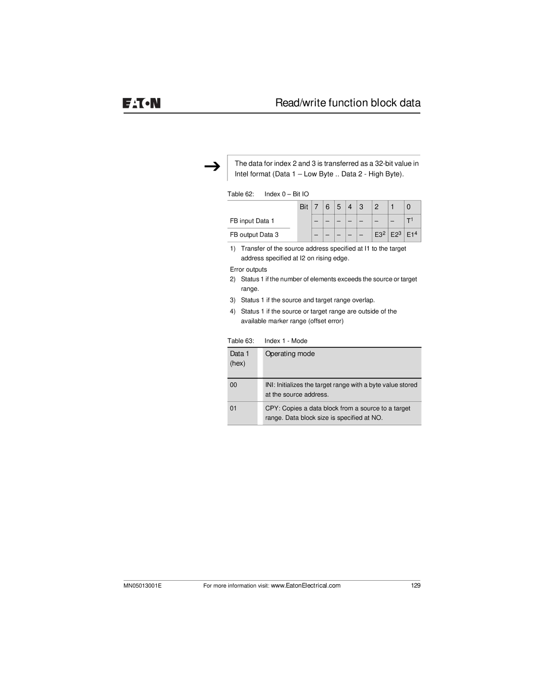
The data for index 2 and 3 is transferred as a
Table 62: Index 0 – Bit IO
|
| Bit | 7 | 6 | 5 | 4 | 3 | 2 | 1 | 0 |
FB input Data 1 |
|
| – | – | – | – | – | – | – | T1 |
FB output Data 3 |
| – | – | – | – | – | E32 | E23 | E14 | |
1)Transfer of the source address specified at I1 to the target address specified at I2 on rising edge.
Error outputs
2)Status 1 if the number of elements exceeds the source or target range.
3)Status 1 if the source and target range overlap.
4)Status 1 if the source or target range are outside of the available marker range (offset error)
Table 63: Index 1 - Mode
Data 1 Operating mode (hex)
00INI: Initializes the target range with a byte value stored at the source address.
01CPY: Copies a data block from a source to a target range. Data block size is specified at NO.
MN05013001E | For more information visit: www.EatonElectrical.com | 129 |
