Read/write function block data
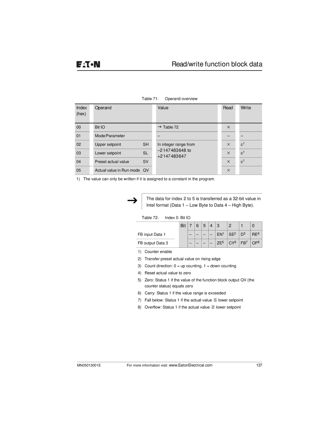
Table 71: Operand overview
Index |
| Operand |
|
| Value |
| Read |
| Write |
(hex) |
|
|
|
|
|
|
|
|
|
|
|
|
|
|
|
|
|
|
|
00 |
| Bit IO |
|
| J Table 72 |
| × |
|
|
01 |
| Mode/Parameter |
|
| – |
| – |
| – |
|
|
|
|
|
|
|
|
|
|
02 |
| Upper setpoint | SH |
| In integer range from |
| × |
| c1 |
|
|
|
|
|
|
|
|
| |
03 |
| Lower setpoint | SL |
|
| × |
| c1 | |
|
| +2147483647 |
|
| |||||
04 |
| Preset actual value | SV |
|
| × |
| c1 | |
|
|
|
|
| |||||
05 |
| Actual value in Run mode | QV |
|
|
| × |
|
|
1) The value can only be written if it is assigned to a constant in the program. |
|
|
|
| |||||
J
The data for index 2 to 5 is transferred as a
Table 72: Index 0: Bit IO
|
| Bit | 7 | 6 | 5 | 4 | 3 | 2 | 1 | 0 |
FB input Data 1 |
|
| – | – | – | – | EN1 | SE2 | D3 | RE4 |
FB output Data 3 |
| – | – | – | – | ZE5 | CY6 | FB7 | OF8 | |
1)Counter enable
2)Transfer preset actual value on rising edge
3)Count direction: 0 = up counting, 1 = down counting
4)Reset actual value to zero
5)Zero: Status 1 if the value of the function block output QV (the counter status) equals zero
6)Carry: Status 1 if the value range is exceeded
7) | Fall below: Status 1 if the actual value | lower setpoint |
8) | Overflow: Status 1 if the actual value | lower setpoint |
MN05013001E | For more information visit: www.EatonElectrical.com | 137 |