Read/write function block data
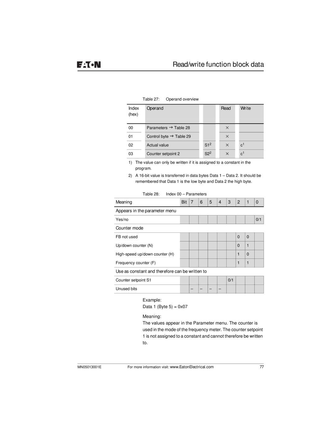
Table 27: Operand overview
Index | Operand |
|
|
| Read |
| Write | |
(hex) |
|
|
|
|
|
|
| |
|
|
|
|
|
|
|
|
|
00 |
| Parameters J Table 28 |
|
|
| × |
|
|
01 |
| Control byte J Table 29 |
|
|
| × |
|
|
|
|
|
|
|
|
|
|
|
02 |
| Actual value |
| S12 |
| × |
| c1 |
03 |
| Counter setpoint 2 |
| S22 |
| × |
| c1 |
1)The value can only be written if it is assigned to a constant in the program.
2)A
Table 28: | Index 00 – Parameters |
|
|
|
|
|
| |||
|
|
|
|
|
|
|
|
|
|
|
Meaning |
| Bit | 7 | 6 | 5 | 4 | 3 | 2 | 1 | 0 |
Appears in the parameter menu |
|
|
|
|
|
|
|
| ||
|
|
|
|
|
|
|
|
|
|
|
Yes/no |
|
|
|
|
|
|
|
|
| 0/1 |
Counter mode |
|
|
|
|
|
|
|
|
|
|
|
|
|
|
|
|
|
|
|
|
|
FB not used |
|
|
|
|
|
|
| 0 | 0 |
|
Up/down counter (N) |
|
|
|
|
|
|
| 0 | 1 |
|
|
|
|
|
|
|
|
|
| ||
|
|
|
|
|
| 1 | 0 |
| ||
Frequency counter (F) |
|
|
|
|
|
|
|
|
|
|
|
|
|
|
|
|
| 1 | 1 |
| |
|
|
|
|
|
|
|
|
|
| |
Use as constant and therefore can be | written | to |
|
|
|
|
|
| ||
|
|
|
|
|
|
|
|
|
|
|
Counter setpoint S1 |
|
|
|
|
|
| 0/1 |
|
|
|
|
|
|
|
|
|
|
|
|
|
|
Unused bits |
|
| – | – | – | – |
|
|
|
|
|
|
|
|
|
|
|
|
|
|
|
Example:
Data 1 (Byte 5) = 0x07
Meaning:
The values appear in the Parameter menu. The counter is used in the mode of the frequency meter. The counter setpoint 1 is not assigned to a constant and cannot therefore be written to.
MN05013001E | For more information visit: www.EatonElectrical.com | 77 |