EZ800/EZD Control Commands
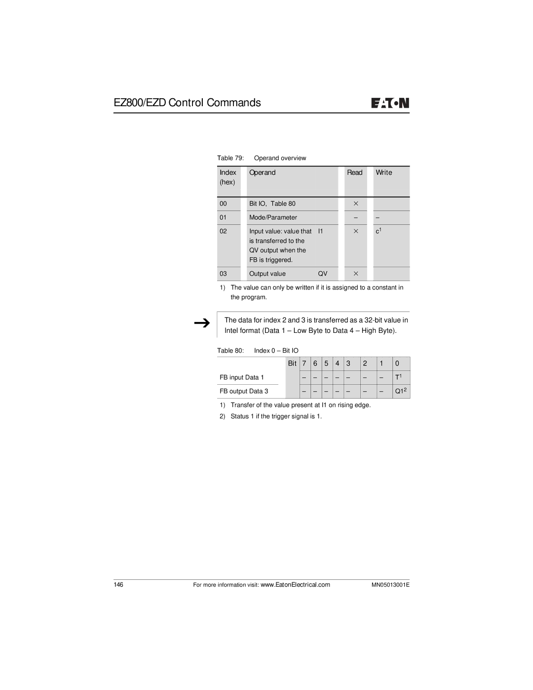
Table 79: | Operand overview |
|
|
|
|
| |
|
|
|
|
|
|
|
|
Index |
| Operand |
|
| Read |
| Write |
(hex) |
|
|
|
|
|
|
|
|
|
|
|
|
|
|
|
00 |
| Bit IO, Table 80 |
|
| × |
|
|
01 |
| Mode/Parameter |
|
| – |
| – |
|
|
|
|
|
|
|
|
02 |
| Input value: value that | I1 |
| × |
| c1 |
|
| is transferred to the |
|
|
|
|
|
|
| QV output when the |
|
|
|
|
|
|
| FB is triggered. |
|
|
|
|
|
03 |
| Output value | QV |
| × |
|
|
|
|
|
|
|
|
|
|
1)The value can only be written if it is assigned to a constant in the program.
J
The data for index 2 and 3 is transferred as a
Table 80: Index 0 – Bit IO
|
| Bit | 7 | 6 | 5 | 4 | 3 | 2 | 1 | 0 |
FB input Data 1 |
|
| – | – | – | – | – | – | – | T1 |
FB output Data 3 |
| – | – | – | – | – | – | – | Q12 | |
1)Transfer of the value present at I1 on rising edge.
2)Status 1 if the trigger signal is 1.
146 | For more information visit: www.EatonElectrical.com | MN05013001E |