Control commands for EZ700
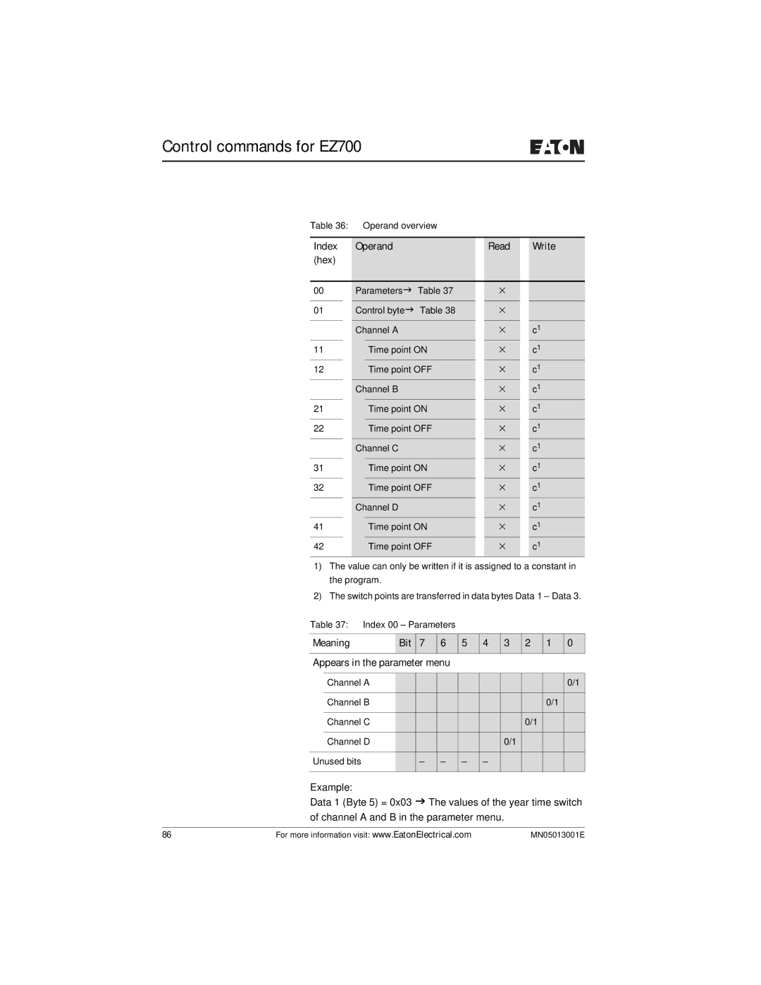
Table 36: | Operand overview |
|
|
|
| |||
|
|
|
|
|
|
|
|
|
| Index | Operand |
| Read |
| Write | ||
| (hex) |
|
|
|
|
|
| |
|
|
|
|
|
|
|
| |
| 00 |
| ParametersJ Table 37 |
| × |
|
| |
| 01 |
| Control byteJ Table 38 |
| × |
|
| |
|
|
|
|
|
|
|
|
|
|
|
| Channel A |
| × |
| c1 | |
| 11 |
|
| Time point ON |
| × |
| c1 |
12 |
|
| Time point OFF |
| × |
| c1 | |
|
|
| Channel B |
| × |
| c1 | |
| 21 |
|
| Time point ON |
| × |
| c1 |
22 |
|
| Time point OFF |
| × |
| c1 | |
|
|
| Channel C |
| × |
| c1 | |
| 31 |
|
| Time point ON |
| × |
| c1 |
32 |
|
| Time point OFF |
| × |
| c1 | |
|
|
| Channel D |
| × |
| c1 | |
| 41 |
|
| Time point ON |
| × |
| c1 |
| 42 |
|
| Time point OFF |
| × |
| c1 |
1)The value can only be written if it is assigned to a constant in the program.
2)The switch points are transferred in data bytes Data 1 – Data 3.
Table 37: Index 00 – Parameters
Meaning | Bit | 7 | 6 |
|
|
|
|
5 4 3 2 1 0
Appears in the parameter menu
| Channel A |
|
|
|
|
|
|
|
| 0/1 |
| Channel B |
|
|
|
|
|
|
| 0/1 |
|
| Channel C |
|
|
|
|
|
| 0/1 |
|
|
|
|
|
|
|
|
|
|
|
|
|
| Channel D |
|
|
|
|
| 0/1 |
|
|
|
|
|
|
|
|
|
|
|
|
| |
Unused bits |
| – | – | – | – |
|
|
|
| |
|
|
|
|
|
|
|
|
|
|
|
Example:
Data 1 (Byte 5) = 0x03 J The values of the year time switch of channel A and B in the parameter menu.
86 | For more information visit: www.EatonElectrical.com | MN05013001E |