HP DesignJets 500, 510 and 800 Series Large-Format Printers
Safety Symbols
HP DesignJets 500, 510 and 800 Series Large-Format Printers
Readership Part Numbers
Using this Manual
Purpose
Conventions
Table of Contents
Service Calibrations
Service Tests and Utilities
Print Quality
Parts and Diagrams
Removal and Installation
Glossary Index
Preventive Maintenance
Functional Overview
Troubleshooting
Introduction
Guide to Troubleshooting the Printer
Performing the Necessary Service Calibrations
Troubleshooting System Error Codes
Performing a Service Test on a Failed Assembly
Printer does not Power on
Solving Print Quality Problems
Line Sensor has Problems Detecting Media
Cover Sensors are not Working
Troubleshooting Paper-Axis Shutdowns
Vacuum suction much lower at high altitudes
Problems with the Vacuum Fan
Banding at variable extreme environmental conditions
HP-GL/2 color differences in different HP DesignJet Printers
Priming Procedure Fails
Check for ink
Troubleshooting
Does not Power up completely. The LED may flash in other
Using the Power Switch LED to Troubleshoot
Mean that there is a problem with the Printer
Circumstances which are completely normal and this does not
Page
Using the Boot-Up Sequence to Troubleshoot
Entering Service Menu at Power Up Only for Onsite Repair
LED’s on the Formatter
Using the Formatter/Accessory Card LEDs to Troubleshoot
LED’s on the HP-GL/2 Accessory Card
Page
Encoder Disk
How to Detect Problems Related to the Encoder Disk
System Error Codes
System Error Codes Explanation
Continuable and Non-Continuable Error Codes
To troubleshoot the problem
Even though the customer can continue working with a
System Error Codes
Code Recovery Action Response
Accessing the Error Log Utility
Error Log Utility
Front panel will return to the previous screen
To view information on another Error Code, press Back
System Error Problem Description Corrective Action
0113 Electronics Module failure. The possible cause could be
Error Only applicable to HP DesignJet 800 Series
Error Only applicable to HP DesignJet 500 and 510 Series
Problem Description Corrective Action System Error
Replace the Ink Supply Station ⇒
4110
5610
Front Panel Set-up menu / PS settings / Encoding / Binary
7104
7204
7904
8510
8613
Carriage-Axis shutdown Firmware Error
Ink Supplies Troubleshooting
Ink Cartridges
What are the Ink Supplies?
Magenta and Yellow colors. The HP No.11 Ink Cartridges
Contain 33cc of ink
Identifying the Components
Printheads
General Information About the Ink Supplies
Some General Precautions When Handling the Ink Supplies
When Should You Replace the Ink Cartridges?
When Should You Replace the Printheads?
Worn out Printhead
User can continue using the Printer even with the Printhead
That the Printer is designed to provide, unless he replaces
Press the Enter key
Obtaining Ink Cartridge Information
Obtaining Printhead Information
Front panel displays information on the selected Printhead
Page
Ink Cartridge Status While Replacing
Ink Cartridge Status Messages
Printhead Status Messages
Printhead History Utility
Accessing the Printhead History Utility
Log Printheads Errors Menu Back Enter
Is the Printer Causing Repetitive Printhead Problems?
Summary
Is the User Replacing the Printheads too Early?
Summary
Ink Cartridge Error message
Troubleshooting Repetitive Ink Cartridge Messages
Ink Cartridge is leaking. In this case try the following
Out of Ink message
Printhead Error message
Troubleshooting Repetitive Printhead Error Messages
Expiration message
Order to determine the correct date, the Printer reads
Code Explanation
Printhead Error Codes
Summary of Solving Ink Supplies Problems
Service Tests Utilities
Introduction
Diagnostics Self Test
Phone Support
Initialization Sequences
Service Tests Diagnostics
Instructions on
Entering the Service Tests Menu
Order to enter the Service Utility Menu, please refer to
Page
Ink Supply Station
If this Test PASSES, do not Replace the INK
Carriage Movement
Normal Values Acceptable Values PWM Average
45 mm 65 mm
Lowered before performing this test
Paper Advance Test
Remove any media loaded and make sure that Pinch-Arms are
Following message will be displayed
If the test fails while checking the Paper-Axis Motor, then
You will be able to determine exactly which component failed
Service Utilities
Entering the Service Utilities Menu
Page
After any change in the EEROM, switch the Printer OFF
Eerom Setup
Subsystems of the Printer
If you want to select the Serial Number
B C D E F ES SG
If you want to change the Font Type
Counter for a component when it has not been replaced
If you want to Reset the Usage Counter
Menu
Operation
Turn Drive Roller
Carriage will remain uncapped until another action e.g
Unlock Carriage
Printer to normal operation. Make sure you leave
Carriage in a locked position once the repair is completed
Prime Tubes
Change Cutter
Service Tests and Utilities
To a position where it can be replaced
Change Ink Tubes
Printer Information
Some of the parameters can be reset to zero by using
Eerom Setup utility ⇒
How to convert the Service ID into a calendar date
Page
Service Calibrations
Service Calibrations
Entering the Service Calibrations Menu
Page
Perform the Printhead Alignment as follows
Printhead Alignment includes PPS Calibration
Make sure you use HP Bright White InkJet Paper Bond, HP
Coated Paper, HP Heavy Coated Paper, HP High-Gloss Paper
Aligning printheads Please wait
Make sure you load media before performing this calibration
Color Calibration
Calibration error Press Enter to continue Menu Back
Advance Calibration
Job management menu
Factory Advance Calibration
Photo Paper or HP Bright White Inkjet Paper
Do not use any other type of media apart from HP High Gloss
Job management menu
Print Quality
Print Quality
Print Quality Troubleshooting Checklist
Accuracy Calibration
Photo Paper or Bright White InkJet Paper when performing
What is the Troubleshooting Procedure?
How to Use the Troubleshooting Procedure
Considerations for Using the Troubleshooting Procedure
Performing the Troubleshooting Procedure
Loaded and takes several minutes to perform
Printhead Alignment requires a few centimeters of Paper
Ignore these solid bars
Start Here
Troubleshooting Procedure Flowchart
What to Configure Configuration Setting Optimal Setting
Long Term Color Bleeding Glossy Papers
Solving Color Accuracy problems
Color Consistency problems
There are Smears or Scratching on the Printed Media
Media
Parts and Diagrams
Printer Support
Printer Support
Right Hand Cover
Right Hand Cover
Left Hand Cover
Left Hand Cover
Top Cover and Deflectors
Top Cover and Deflectors
Rollfeed Module
Rollfeed Module
Back Platen Assembly
Back Platen Assembly
Electronics Module
Refer to the following page for more details
Cooling fan orientation for the HP DesignJet 500 Printer
Cooling Fan
Series serial number MY857H307G and greater, and all
HP DesignJet 510 Series Printers, is as shown below
HP Part Number Quantity Description/Comments Drawing
Power Supply
Power Supply
Power Supply
Cutter Assemblies
Cutter Assemblies
Cutter Assemblies
Ink Delivery System
Ink Delivery System
Ink Delivery System
Service Station and Spittoon
Service Station and Spittoon
Service Station and Spittoon
Service Station Holder
Service Station Holder
Service Station Holder
Pinch-Wheel Assemblies
Pinch-Wheel Assemblies
Pinch-Wheel Assemblies
Scan-Axis Motor
Scan-Axis Motor
Scan-Axis Motor
Drive Roller Encoder Sensor
Drive Roller Encoder Sensor
Drive Roller Encoder Sensor
Print Platen Assembly
Print Platen Assembly
Print Platen Assembly
Carriage Assembly
Carriage Assembly
Carriage Assembly
Vacuum Fan
Parts and Diagrams
Vacuum Fan
Vacuum Fan
Interconnect Cable
Interconnect Cable
Interconnect Cable
Paper-Axis Motor
Paper-Axis Motor
Paper-Axis Motor
Drive Roller
Drive Roller
Drive Roller
Miscellaneous Items
Miscellaneous Items
Removal and Installation
Safety Precautions
Required Tools
Electrostatic Discharge ESD Precautions
Screw Types
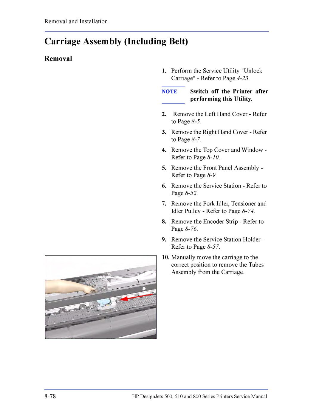
Removal
Left Hand Cover
Page
Back of the Right Hand Cover
Right Hand Cover
Remove 1 T-20 screw Type F from
Page
Front Panel
Window and Top Cover
Media Deflectors
Switch off the printer and remove the power cord
Page
Left End Roll-Feed
Switch off the printer and remove the power cord
Page
Right End Roll-Feed
Removal and Installation Remove Right Hand Roll-Feed
Back Platen
Page
Media Sensor
Back of the Left Hand Cover
Formatter
Remove the LAN Card Cover from
LAN Card
Page
Release
Spittoon
Disconnect ALL the cables from
Electronics Module
Remove the Left Hand Cover Refer
Loosen Only
Installing the Electronics Module
Disconnect
Power Supply
Page
Scan-Axis Motor Assembly
Page
Installing the Scan-Axis Motor
Select the Change Cutter option
Cutter Assembly
From the Front Panel Menu
Open the Window
Left Encoder Holder
Page
Cutter Bushing
Remove the Cutter from its position
Cutter Guide Bracket
Page
Drive Roller Encoder Sensor
Page
Trailing Cable
Page
Page
Page
Page
Page
Page
Installing the Trailing Cable
Ink Supply Station
Assembly must be removed
Assembly that includes
Installed together
ISS is a complete
Remove the Right Hand Cover Refer
Interconnect PCA
Disconnect all the cables connected to
Interconnect PCA
Page
Service Station and Aerosol Fan
Page
Installing the Service Station/Aerosol Fan
Cutter Guide
Print Platen
Service Station Holder
Page
Interconnect Cable
Ink Supply Tubes
Page
Page
Page
Vacuum Fan
Page
Pinch-Arm
Pinch-Arm Mechanism
Page
Pinch-Arm Lever
Page
Raise the Media Lever
Pinch-Arm Sensor
Page
Page
Fork Idler, Tensioner and Idler Pulley
Page
Encoder Strip
Release
Carriage Assembly Including Belt
Page
Page
Page
Page
Installing the Carriage Assembly
Paper-Axis Motor
Page
Drive Roller
Page
Page
Page
Page
Page
Gear Assemblies
Page
Preventive Maintenance
Preventive Maintenance
Level of Printer Usage
Cleaning the Drive Roller/Print Platen
Scheduled Maintenance
Scan-Axis Maintenance
Functional Overview
Total there are 12 SKUs. They are detailed as follows
SKU Overview
Functional Overview
Hardware Description
Electrical System
Page
Power Supply Connector to Main PCA Power Switch Housing
Power Supply Unit PSU
Voltage Maximum Output Systems
Front Panel
Ink Supply Station ISS
Ink Delivery System IDS
10-9
Tubes System ISS Crane Clips Carriage Crane
Tubes Assembly
Service Station
Ansi size
Default
Application
Centronics
Matte
Margin
Input/output
Inked area
Pen
Raster
Platen
Printing area
About this Edition
Large-Format Printers
Index
Page
Page