Technical Reference Guide
5.7.3 USB CONNECTOR
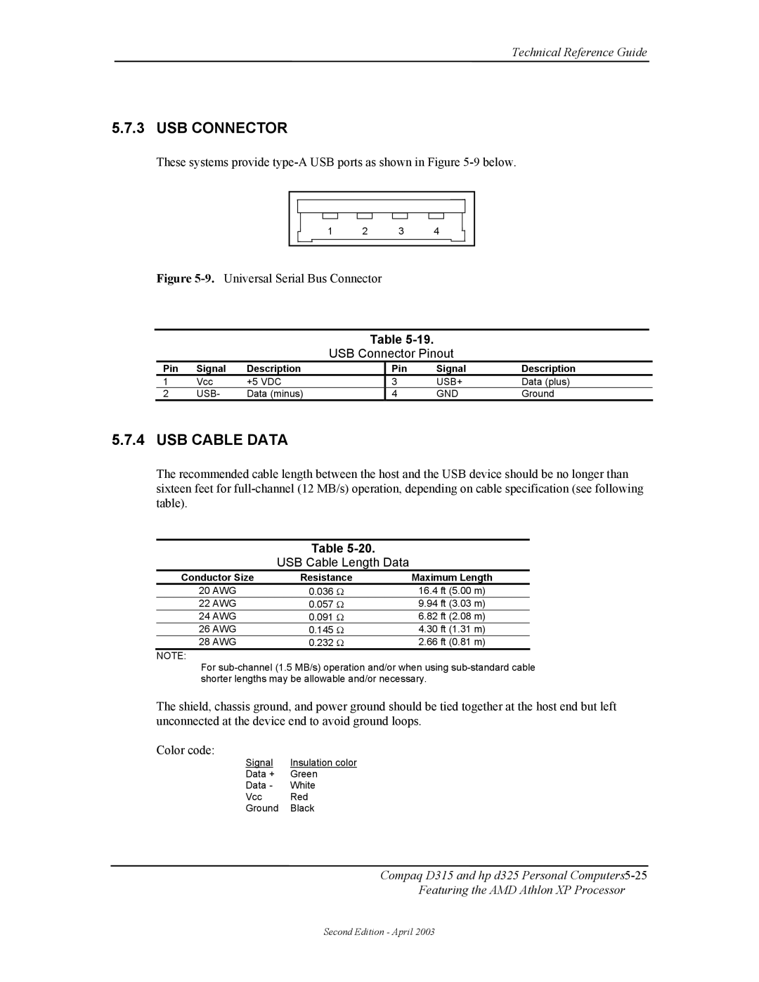
These systems provide
|
|
|
|
|
|
|
|
|
|
|
|
|
|
|
|
|
|
|
|
|
|
|
|
|
|
|
|
|
|
|
|
|
1 | 2 | 3 | 4 |
|
| |||||
|
|
|
|
|
|
|
|
|
|
|
Figure 5-9. Universal Serial Bus Connector
Table 5–19. USB Connector Pinout
Table
USB Connector Pinout
Pin | Signal | Description | Pin | Signal | Description |
1 | Vcc | +5 VDC | 3 | USB+ | Data (plus) |
2 | USB- | Data (minus) | 4 | GND | Ground |
5.7.4 USB CABLE DATA
The recommended cable length between the host and the USB device should be no longer than sixteen feet for
Table
Table
USB Cable Length Data
Conductor Size | Resistance | Maximum Length |
20 AWG | 0.036 Ω | 16.4 ft (5.00 m) |
22 AWG | 0.057 Ω | 9.94 ft (3.03 m) |
24 AWG | 0.091 Ω | 6.82 ft (2.08 m) |
26 AWG | 0.145 Ω | 4.30 ft (1.31 m) |
28 AWG | 0.232 Ω | 2.66 ft (0.81 m) |
NOTE:
For
The shield, chassis ground, and power ground should be tied together at the host end but left unconnected at the device end to avoid ground loops.
Color code:
Signal | Insulation color |
Data + | Green |
Data - | White |
Vcc | Red |
Ground | Black |
Compaq D315 and hp d325 Personal
Featuring the AMD Athlon XP Processor
Second Edition - April 2003
