Technical Reference Guide
The DMA logic is accessed through two types of I/O mapped registers; page registers and controller registers.
4.4.2.1DMA Page Registers
The DMA page register contains the eight most significant bits of the
Table
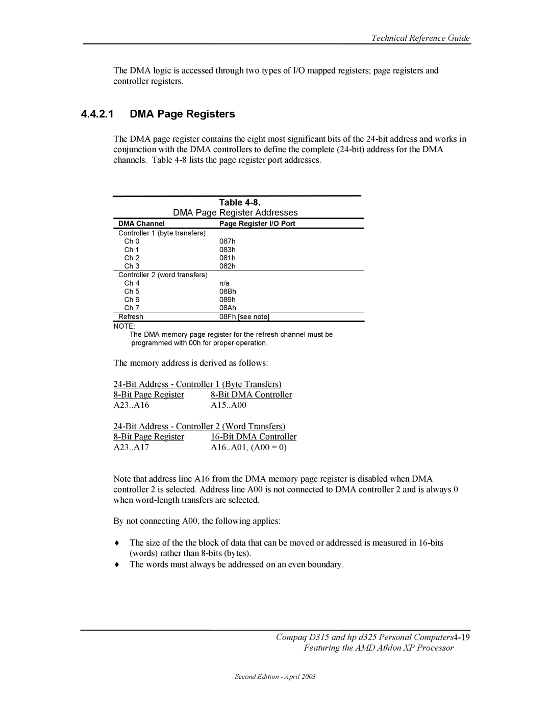
| Table |
DMA Page Register Addresses | |
DMA Channel | Page Register I/O Port |
Controller 1 (byte transfers) |
|
Ch 0 | 087h |
Ch 1 | 083h |
Ch 2 | 081h |
Ch 3 | 082h |
Controller 2 (word transfers) |
|
Ch 4 | n/a |
Ch 5 | 08Bh |
Ch 6 | 089h |
Ch 7 | 08Ah |
Refresh | 08Fh [see note] |
NOTE:
The DMA memory page register for the refresh channel must be programmed with 00h for proper operation.
The memory address is derived as follows:
A23..A16 | A15..A00 |
A23..A17 | A16..A01, (A00 = 0) |
Note that address line A16 from the DMA memory page register is disabled when DMA controller 2 is selected. Address line A00 is not connected to DMA controller 2 and is always 0 when
By not connecting A00, the following applies:
♦The size of the the block of data that can be moved or addressed is measured in
♦The words must always be addressed on an even boundary.
Compaq D315 and hp d325 Personal
Featuring the AMD Athlon XP Processor
Second Edition - April 2003