Chapter 4 System Support
4.2PCI BUS OVERVIEW
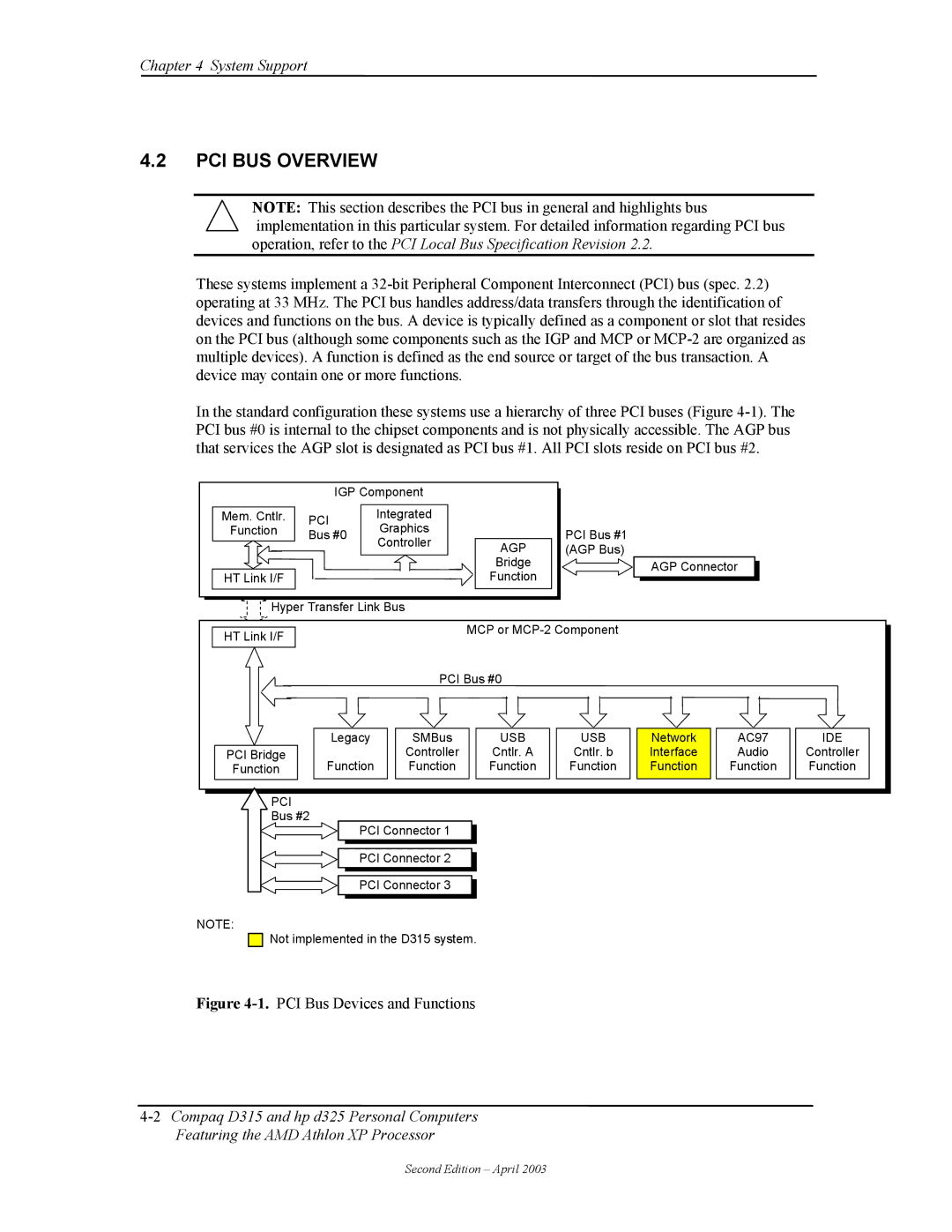
NOTE: This section describes the PCI bus in general and highlights bus implementation in this particular system. For detailed information regarding PCI bus operation, refer to the PCI Local Bus Specification Revision 2.2.
These systems implement a
In the standard configuration these systems use a hierarchy of three PCI buses (Figure
| IGP Component |
|
| |
Mem. Cntlr. | PCI | Integrated |
|
|
Function | Graphics |
|
| |
Bus #0 |
| PCI Bus #1 | ||
| Controller | AGP | ||
|
| (AGP Bus) | ||
|
|
| Bridge | AGP Connector |
HT Link I/F |
|
| Function | |
|
|
| ||
Hyper Transfer Link Bus |
|
|
|
|
|
| |
HT Link I/F |
|
| MCP or |
|
|
| |
|
|
|
|
|
|
| |
|
| PCI Bus #0 |
|
|
|
| |
| Legacy | SMBus | USB | USB | Network | AC97 | IDE |
PCI Bridge |
| Controller | Cntlr. A | Cntlr. b | Interface | Audio | Controller |
Function | Function | Function | Function | Function | Function | Function | Function |
PCI |
|
|
|
|
|
|
|
Bus #2 |
|
|
|
|
|
|
|
PCI Connector 1
PCI Connector 2
PCI Connector 3
NOTE:
![]()
![]() Not implemented in the D315 system.
Not implemented in the D315 system.
Figure 4-1. PCI Bus Devices and Functions
Second Edition – April 2003