Chapter 4 System Support
The systems covered in this guide utilize the following specialized functions built into the LPC47B367 I/O Controller:
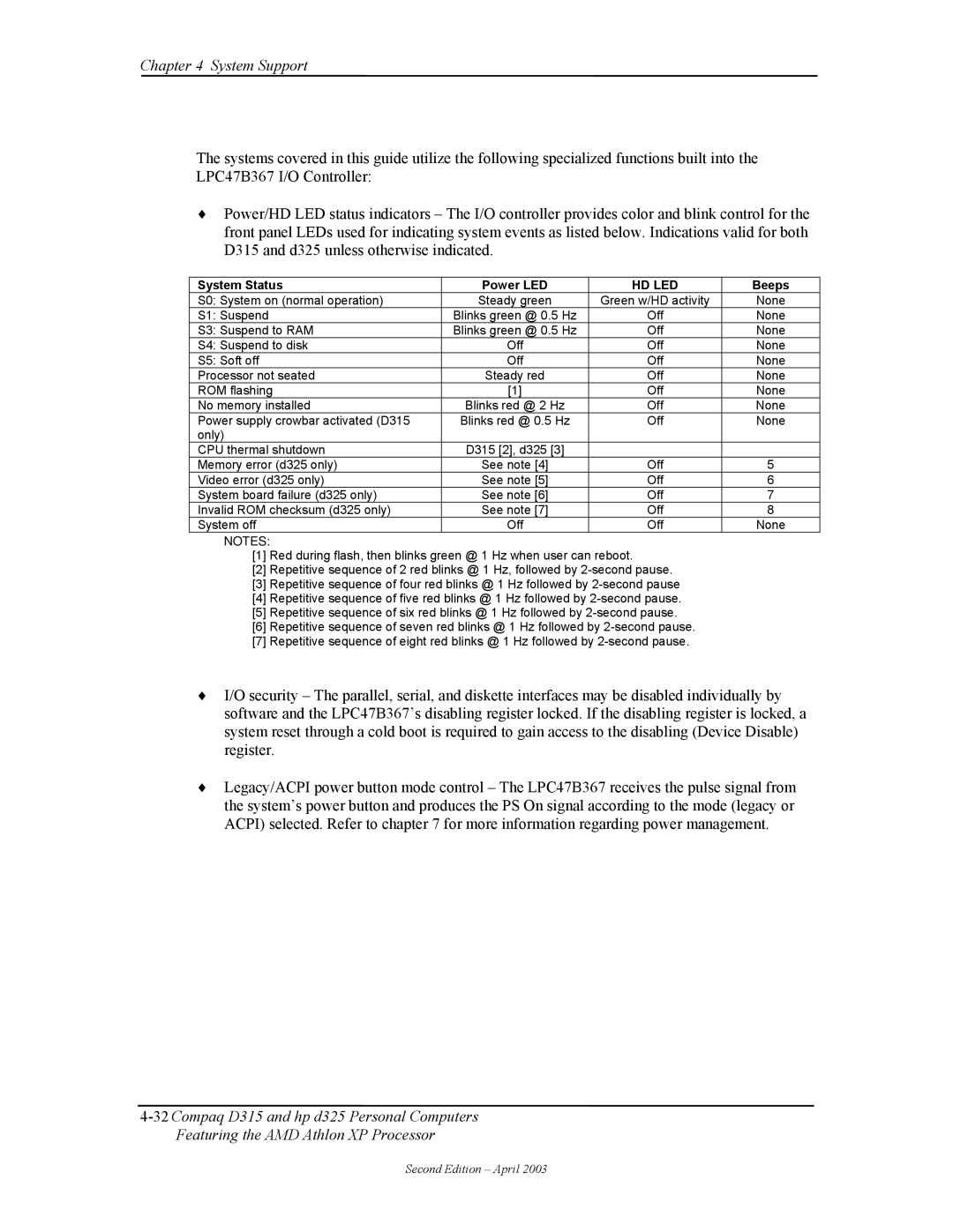
♦Power/HD LED status indicators – The I/O controller provides color and blink control for the front panel LEDs used for indicating system events as listed below. Indications valid for both D315 and d325 unless otherwise indicated.
System Status | Power LED | HD LED | Beeps |
S0: System on (normal operation) | Steady green | Green w/HD activity | None |
S1: Suspend | Blinks green @ 0.5 Hz | Off | None |
S3: Suspend to RAM | Blinks green @ 0.5 Hz | Off | None |
S4: Suspend to disk | Off | Off | None |
S5: Soft off | Off | Off | None |
Processor not seated | Steady red | Off | None |
ROM flashing | [1] | Off | None |
No memory installed | Blinks red @ 2 Hz | Off | None |
Power supply crowbar activated (D315 | Blinks red @ 0.5 Hz | Off | None |
only) |
|
|
|
CPU thermal shutdown | D315 [2], d325 [3] |
|
|
Memory error (d325 only) | See note [4] | Off | 5 |
Video error (d325 only) | See note [5] | Off | 6 |
System board failure (d325 only) | See note [6] | Off | 7 |
Invalid ROM checksum (d325 only) | See note [7] | Off | 8 |
System off | Off | Off | None |
NOTES:
[1]Red during flash, then blinks green @ 1 Hz when user can reboot.
[2]Repetitive sequence of 2 red blinks @ 1 Hz, followed by
[3]Repetitive sequence of four red blinks @ 1 Hz followed by
[4]Repetitive sequence of five red blinks @ 1 Hz followed by
[5]Repetitive sequence of six red blinks @ 1 Hz followed by
[6]Repetitive sequence of seven red blinks @ 1 Hz followed by
[7]Repetitive sequence of eight red blinks @ 1 Hz followed by
♦I/O security – The parallel, serial, and diskette interfaces may be disabled individually by software and the LPC47B367’s disabling register locked. If the disabling register is locked, a system reset through a cold boot is required to gain access to the disabling (Device Disable) register.
♦Legacy/ACPI power button mode control – The LPC47B367 receives the pulse signal from the system’s power button and produces the PS On signal according to the mode (legacy or ACPI) selected. Refer to chapter 7 for more information regarding power management.
Second Edition – April 2003
