Technical Reference Guide
7.4SIGNAL DISTRIBUTION
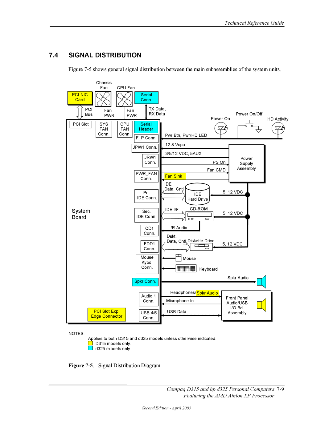
Figure 7-5 shows general signal distribution between the main subassemblies of the system units.
| Chassis |
|
|
|
|
|
|
| Fan | CPU Fan |
|
|
|
|
|
PCI NIC |
|
| Serial |
|
|
|
|
Card |
|
| Conn. |
|
|
|
|
PCI | Fan | Fan | TX Data, |
|
| Power On/Off | |
Bus | PWR | PWR | RX Data | Power On | |||
PCI Slot | SYS | CPU | Serial |
| HD Activity | ||
|
|
|
| ||||
| FAN | FAN | Header |
|
|
|
|
| Conn. | Conn. |
| Pwr Btn, Pwr/HD LED |
|
| |
|
| F_P Conn. |
|
|
|
| |
|
| JPW1 Conn. | 12.8 Vcpu |
|
|
| |
|
|
|
|
|
| ||
|
|
| JRW1 | 3/5/12 VDC, 5AUX |
| Power | |
|
|
|
| PS On | |||
|
|
| Conn. |
| Supply | ||
|
| PWR_FAN |
| Fan CMD | Assembly | ||
|
|
|
| ||||
|
| Fan Sink |
|
|
| ||
|
|
| Conn. |
|
|
| |
|
|
| IDE |
|
|
| |
|
|
|
|
|
|
| |
|
|
| Pri. | Data, Cntl | IDE | 5, 12 VDC | |
|
|
|
| ||||
|
|
| IDE Conn. |
|
|
| |
|
|
|
| Hard Drive |
|
| |
|
|
|
|
|
|
| |
System |
|
| Sec. | IDE I/F | 5, 12 VDC | ||
Board |
| IDE Conn. |
|
| |||
|
|
|
|
| |||
|
|
| CD1 | L/R Audio |
|
|
|
|
|
| Conn. | Dskt. |
|
|
|
|
|
|
| Diskette Drive |
|
| |
|
|
| FDD1 | Data, Cntl | 5, 12 VDC | ||
|
|
|
|
| |||
|
|
| Conn. |
|
|
|
|
|
|
| Mouse | Mouse |
|
| |
|
|
| Kybd. |
|
|
|
|
|
|
| Conn. |
| Keyboard |
|
|
|
|
|
|
|
|
| |
|
| Spkr Conn. |
|
| Spkr Audio | ||
|
|
|
|
|
| ||
|
|
| Audio 1 | Headphones/ Spkr Audio | Front Panel | ||
|
|
| Microphone In | ||||
|
|
| Conn. | ||||
|
|
| Audio/USB | ||||
|
|
|
|
|
| ||
| PCI Slot Exp. | USB 4/5 | USB Data |
|
| I/O Bd. | |
|
| Assembly | |||||
Edge Connector | Conn. |
|
|
|
| ||
|
|
|
|
|
|
| |
NOTES:
Applies to both D315 and d325 models unless otherwise indicated. ![]()
![]() D315 models only.
D315 models only.
d325 m odels only.
Figure 7-5. Signal Distribution Diagram
Compaq D315 and hp d325 Personal Computers
Featuring the AMD Athlon XP Processor
Second Edition - April 2003