Chapter 2 System Overview
2.3.2 CHASSIS LAYOUT
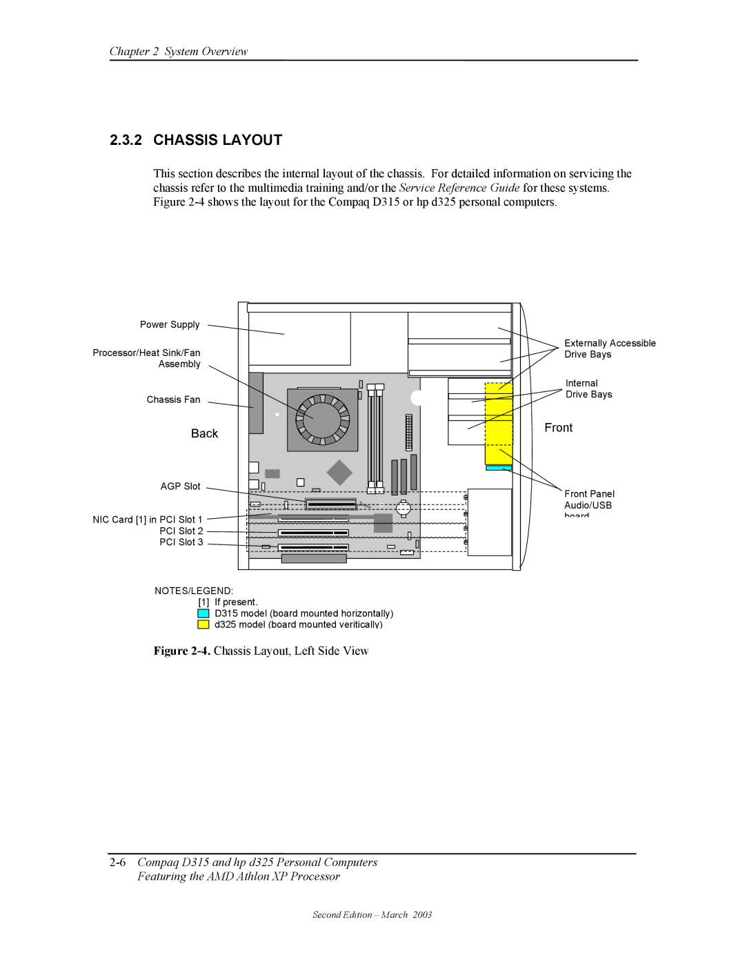
This section describes the internal layout of the chassis. For detailed information on servicing the chassis refer to the multimedia training and/or the Service Reference Guide for these systems. Figure
Power Supply
Processor/Heat Sink/Fan Assembly
Chassis Fan
Back
AGP Slot
NIC Card [1] in PCI Slot 1
PCI Slot 2
PCI Slot 3
Externally Accessible |
Drive Bays |
Internal |
Drive Bays |
Front |
Front Panel |
Audio/USB |
board |
NOTES/LEGEND:
[1] If present.
D315 model (board mounted horizontally) d325 model (board mounted veritically)
Figure 2-4. Chassis Layout, Left Side View
Second Edition – March 2003
