Technical Reference Guide
5.3.1 DISKETTE DRIVE PROGRAMMING
Programming the diskette drive interface consists of configuration, which occurs typically during POST, and control, which occurs at runtime.
5.3.1.1 Diskette Drive Interface Configuration
The diskette drive controller must be configured for a specific address and also must be enabled before it can be used. Address selection and enabling of the diskette drive interface are affected by firmware through the PnP configuration registers of the LPC47B367 I/O controller during POST.
The configuration registers are accessed through I/O registers 2Eh (index) and 2Fh (data) after the configuration phase has been activated by writing 55h to I/O port 2Eh. The diskette drive I/F is initiated by firmware selecting logical device 0 of the LPC47B367 using the following sequence:
1.Write 07h to I/O register 2Eh.
2.Write 00h to I/O register 2Fh (this selects the diskette drive I/F).
3.Write 30h to I/O register 2Eh.
4.Write 01h to I/O register 2Fh (this activates the interface).
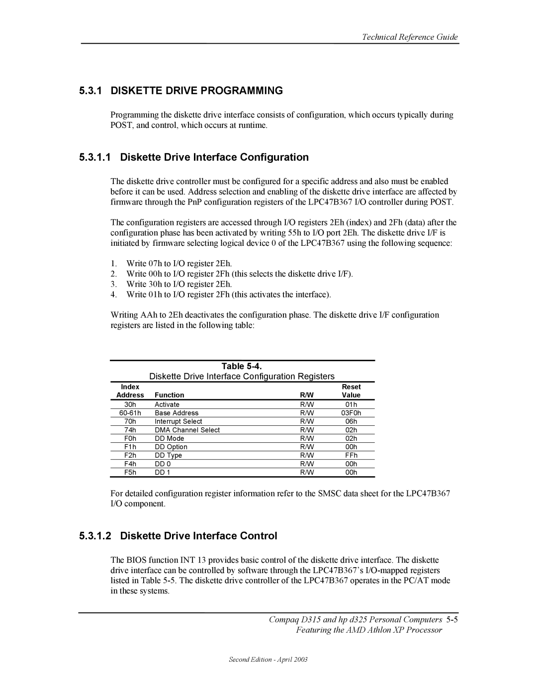
Writing AAh to 2Eh deactivates the configuration phase. The diskette drive I/F configuration registers are listed in the following table:
Table
Table
Diskette Drive Interface Configuration Registers
Index |
|
| Reset |
Address | Function | R/W | Value |
30h | Activate | R/W | 01h |
Base Address | R/W | 03F0h | |
70h | Interrupt Select | R/W | 06h |
74h | DMA Channel Select | R/W | 02h |
F0h | DD Mode | R/W | 02h |
F1h | DD Option | R/W | 00h |
F2h | DD Type | R/W | FFh |
F4h | DD 0 | R/W | 00h |
F5h | DD 1 | R/W | 00h |
For detailed configuration register information refer to the SMSC data sheet for the LPC47B367 I/O component.
5.3.1.2 Diskette Drive Interface Control
The BIOS function INT 13 provides basic control of the diskette drive interface. The diskette drive interface can be controlled by software through the LPC47B367’s
Compaq D315 and hp d325 Personal Computers
Featuring the AMD Athlon XP Processor
Second Edition - April 2003
