Chapter 4 System Support
4.6REAL-TIME CLOCK AND CONFIGURATION MEMORY
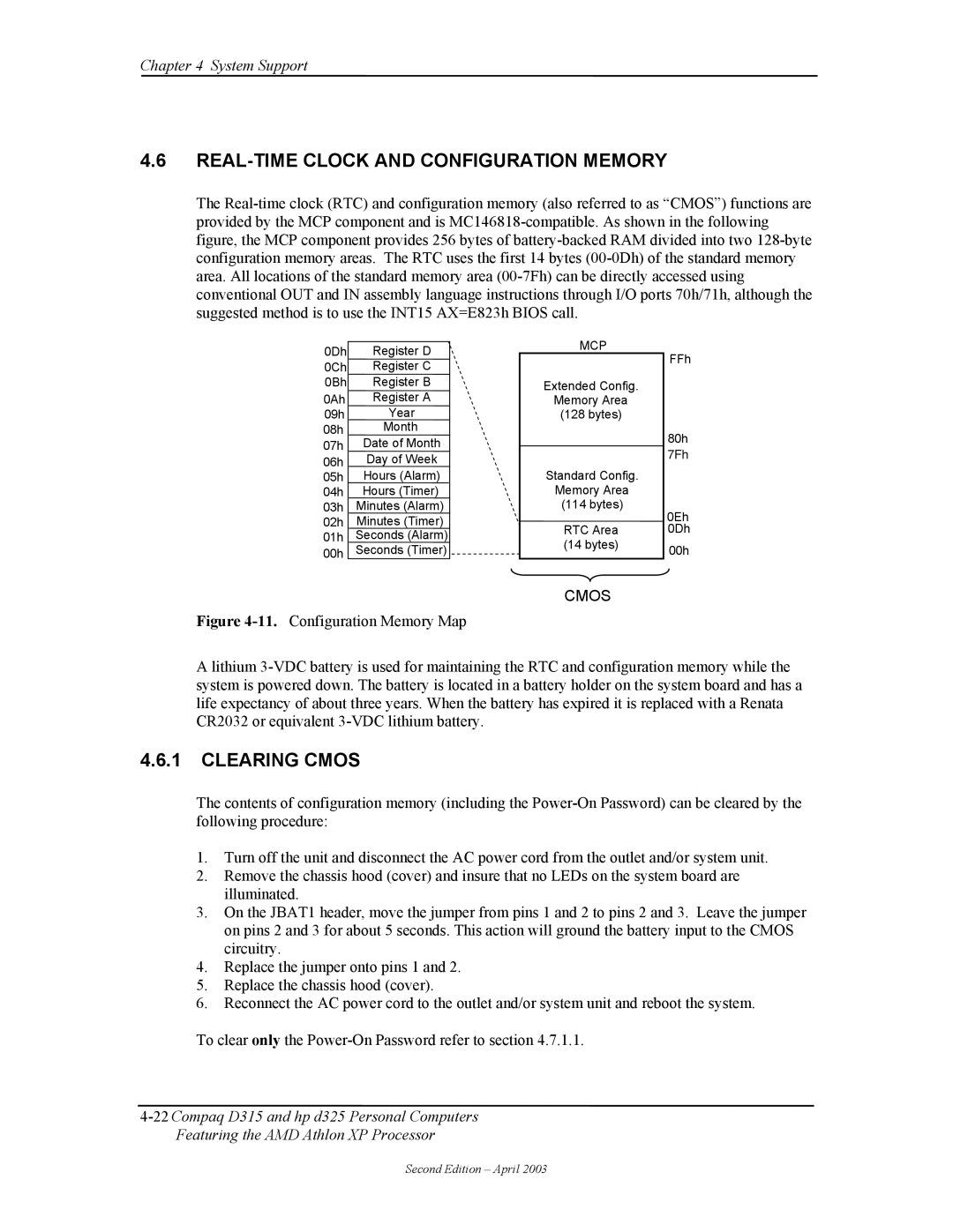
The
0Dh | Register D |
0Ch | Register C |
0Bh | Register B |
0Ah | Register A |
09h | Year |
08h | Month |
07h | Date of Month |
06h | Day of Week |
05h | Hours (Alarm) |
04h | Hours (Timer) |
03h | Minutes (Alarm) |
02h | Minutes (Timer) |
01h | Seconds (Alarm) |
00h | Seconds (Timer) |
MCP
Extended Config.
Memory Area
(128 bytes)
Standard Config.
Memory Area
(114 bytes)
RTC Area (14 bytes)
FFh
80h
7Fh
0Eh
0Dh
00h
CMOS
Figure 4-11. Configuration Memory Map
A lithium 3-VDC battery is used for maintaining the RTC and configuration memory while the system is powered down. The battery is located in a battery holder on the system board and has a life expectancy of about three years. When the battery has expired it is replaced with a Renata CR2032 or equivalent 3-VDC lithium battery.
4.6.1CLEARING CMOS
The contents of configuration memory (including the
1.Turn off the unit and disconnect the AC power cord from the outlet and/or system unit.
2.Remove the chassis hood (cover) and insure that no LEDs on the system board are illuminated.
3.On the JBAT1 header, move the jumper from pins 1 and 2 to pins 2 and 3. Leave the jumper on pins 2 and 3 for about 5 seconds. This action will ground the battery input to the CMOS circuitry.
4.Replace the jumper onto pins 1 and 2.
5.Replace the chassis hood (cover).
6.Reconnect the AC power cord to the outlet and/or system unit and reboot the system.
To clear only the
Second Edition – April 2003
