Technical Reference Guide
4.8.2 LPC47B367 I/O CONTROLLER FUNCTIONS
The LPC47B367 I/O controller contains various functions such as the keyboard/mouse interfaces, diskette interface, serial interfaces, and parallel interface. While the control of these interfaces uses standard
Table
Table
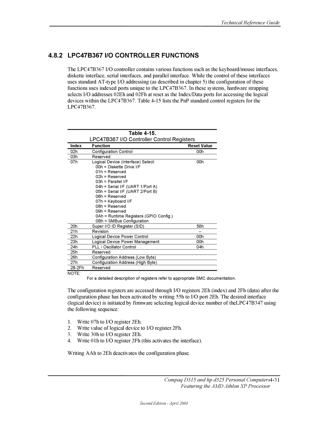
LPC47B367 I/O Controller Control Registers
Index | Function | Reset Value | |
02h | Configuration Control | 00h | |
03h | Reserved |
| |
07h | Logical Device (Interface) Select: | 00h | |
| 00h | = Diskette Drive I/F |
|
| 01h | = Reserved |
|
| 02h | = Reserved |
|
| 03h | = Parallel I/F |
|
| 04h | = Serial I/F (UART 1/Port A) |
|
| 05h | = Serial I/F (UART 2/Port B) |
|
| 06h | = Reserved |
|
| 07h | = Keyboard I/F |
|
| 08h | = Reserved |
|
| 09h | = Reserved |
|
| 0Ah = Runtime Registers (GPIO Config.) |
| |
| 0Bh = SMBus Configuration |
| |
20h | Super I/O ID Register (SID) | 56h | |
21h | Revision | ||
22h | Logical Device Power Control | 00h | |
23h | Logical Device Power Management | 00h | |
24h | PLL / Oscillator Control | 04h | |
25h | Reserved |
| |
26h | Configuration Address (Low Byte) |
| |
27h | Configuration Address (High Byte) |
| |
Reserved |
| ||
NOTE:
For a detailed description of registers refer to appropriate SMC documentation.
The configuration registers are accessed through I/O registers 2Eh (index) and 2Fh (data) after the configuration phase has been activated by writing 55h to I/O port 2Eh. The desired interface (logical device) is initiated by firmware selecting logical device number of theLPC47B347 using the following sequence:
1.Write 07h to I/O register 2Eh.
2.Write value of logical device to I/O register 2Fh.
3.Write 30h to I/O register 2Eh.
4.Write 01h to I/O register 2Fh (this activates the interface).
Writing AAh to 2Eh deactivates the configuration phase.
Compaq D315 and hp d325 Personal
Featuring the AMD Athlon XP Processor
Second Edition - April 2003