Technical Reference Guide
4.5SYSTEM CLOCK DISTRIBUTION
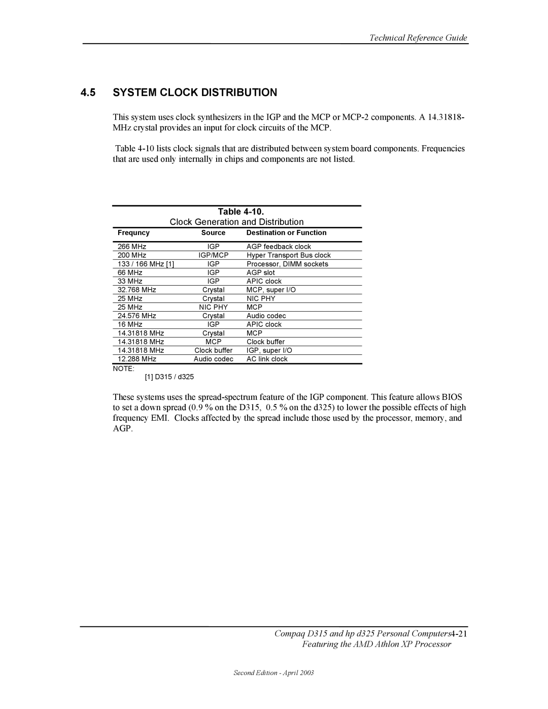
This system uses clock synthesizers in the IGP and the MCP or
Table
Table
Table
Clock Generation and Distribution
Frequncy | Source | Destination or Function |
|
|
|
266 MHz | IGP | AGP feedback clock |
200 MHz | IGP/MCP | Hyper Transport Bus clock |
133 / 166 MHz [1] | IGP | Processor, DIMM sockets |
66 MHz | IGP | AGP slot |
33 MHz | IGP | APIC clock |
32.768 MHz | Crystal | MCP, super I/O |
25 MHz | Crystal | NIC PHY |
25 MHz | NIC PHY | MCP |
24.576 MHz | Crystal | Audio codec |
16 MHz | IGP | APIC clock |
14.31818 MHz | Crystal | MCP |
14.31818 MHz | MCP | Clock buffer |
14.31818 MHz | Clock buffer | IGP, super I/O |
12.288 MHz | Audio codec | AC link clock |
NOTE:
[1] D315 / d325
These systems uses the
Compaq D315 and hp d325 Personal
Featuring the AMD Athlon XP Processor
Second Edition - April 2003
