HP Fabric Clustering System HP-UX Administrators Guide
Copyright 2004-2008 Hewlett-Packard Development Company, L.P
Table of Contents
Configuration
Interfaces
Switch Administration and Management
109
129
131
155
152
154
156
227
217
223
Page
HyperTerminal Login
List of Figures
Page
List of Tables
Default User Names, Passwords and Privileges
Description of Access Levels
Show ib Keyword Descriptions
Show user Command Syntax Descriptions
Show logging Command Syntax Description
Show trace Command Syntax Descriptions
IP Commands
New and Changed Documentation in This Edition
About This Document
Intended Audience
Publishing History
What’s in This Document
Typographical Conventions
Related Documents HP Encourages Your Comments
Related Documents
Page
Understanding InfiniBand
Introduction to Technology
Understanding the Fabric Clustering System
About the HP Fabric Clustering System Software Suite
Interaction with HyperFabric Driver
User-Space Rdma Library
Kernel Rdma Subsystem
About the HP Fabric Clustering System Software Suite
Page
Host Channel Adapters
Hardware Overview
Hardware Components
HP offers the following new Host Channel Adapters HCA
Hardware Overview
AB286C Host Channel Adapter Connector View
AB286C Host Channel Adapter Side View
AB286A Host Channel Adapter Connector View
AB286A Host Channel Adapter Side View
Figureigure
Hardware Components
Switch
Other Product Elements
Hardware Overview
Applications
Installation Planning
Preliminary Considerations
Preliminary Considerations
Application Availability
Installation Planning
Site Set-up
Enter your product name Click the double arrow
Installing HP Fabric Clustering System
HP Fabric Clustering System Installation Prerequisites
Installing HP Fabric Clustering System
Install HP Fabric Clustering System Adapters
Installing the AH304A Host Channel Adapter
Secure the card and reassemble the system
Installing the 410533-B21 Host Channel Adapter
Installing the AD313A Host Channel Adapter
Installing the AB286C Host Channel Adapter
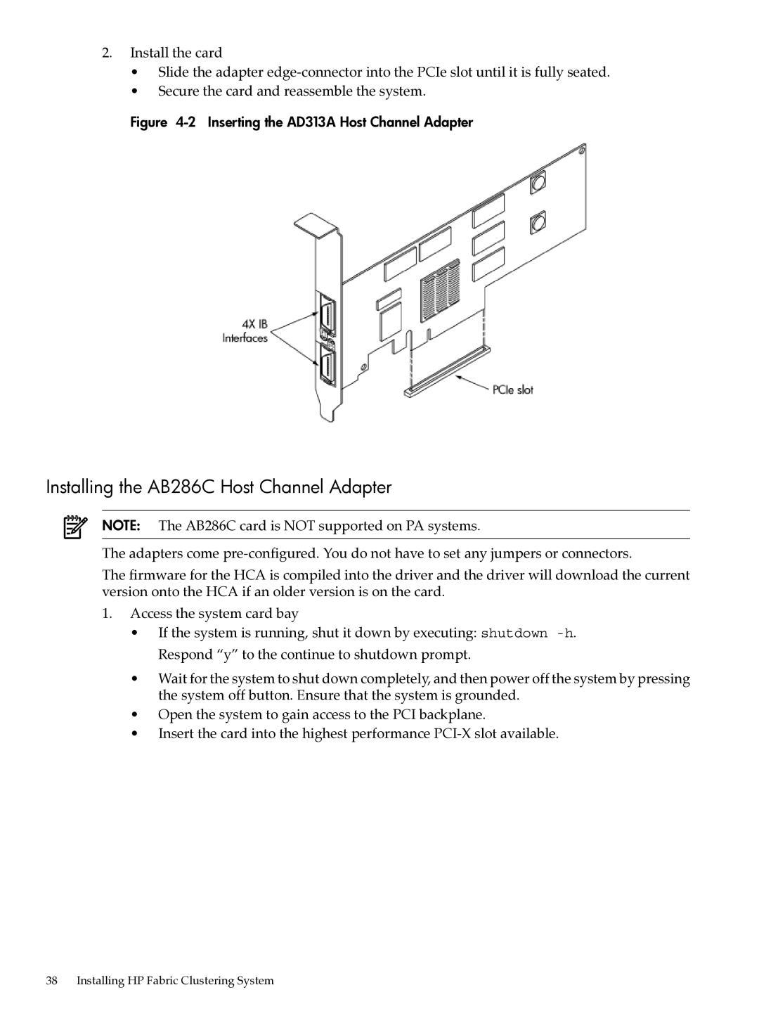
Inserting the AD313A Host Channel Adapter
On-Line Addition and Replacement Operations OL
Inserting the AB286C Host Channel Adapter
This opens the Software Selection window
Install HP Fabric Clustering System Software
Where devicename is the name assigned to the CD-ROM drive
Rack Mount Preparation
Install HP Fabric Clustering System Switches
T-25 Torx screwdrivers Second person for the installation
IB subsystem IB Rdma IPoIB IB device driver ibt
Installing the Switch
Fixed and Sliding Rails
Attach Rail to Switch
Securely attach all rails to the rack
Remove Support Bracket if installed
Remove Shipping Sleeve
Attach Cable Guides & Cables
Attach Cable Guides & Cables
Cable Routing and Bend Limits
Cable Installation Minimum Bend Radius
Attach Cables
Switch or Adapter
Switch Setup
Connect Cables to Switch
Attach to other HP Fabric devices
Set the default gateway address. This address is an example
Setting up the Switch
Enter configure to enter the global-configuration mode
Enable the management port
Internet Protocol over InfiniBand IPoIB
Syntax and Example nwmgr -S ipoib
Page
Configuration Parameters
Configuration
Supported Features
Sample Configurations using the AB286A/C or AD313A HCA
Non-Supported Features
Supported Configurations
Configurations up to 24 End Nodes
Configurations with More Than 24 End Nodes
Sample Configurations using the AB286A/C or AD313A HCA
128 Node 50% non-Blocking Configuration
Administration and Management
Following is a listing of the major topics in this chapter
Administration and Management
HP-UX Host Administration and Management
Using Itutil
Itutil Command Options
Summary of Itutil Command Options
Itutil Administrative Commands
Following syntax must be used with itutil command options
Itutil Management Commands
Syntax itutil Syntax Example itutil Output Example
Syntax Example itutil -i ib0 Output Example
Syntax Example itutil -t IB Output Example
Syntax Example itutil -s-i ib0 Output Example
Administration and Management
Syntax Example itutil -c Output Example
Displaying Connectivity Information Using Itutil
Syntax Example itutil -r Output Example
Example itutil -T
Using NetTL
Viewing the Itutil Manpage
Syntax nettl -llog class -esubsystem
IB Tracing
IPoIB Administration and Management
Ifconfig Command
IPoIB Tracing
Displaying IPoIB Interface Link-Level Information
Lanadmin Commands
Disable the IPoIB Interface To disable the IPoIB interface
Level information for a given ipoibppa
Syntax Example lanadmin -g Output Example
Syntax Example lanadmin -a Output Example
Syntax Example lanadmin -s Output Example
Syntax lanadmin -x-hipoibppa Syntax Example lanadmin -x -h
Introduction
Serviceguard and IPoIB
Lanscan Command
Configuring IPoIB Interfaces for Serviceguard Clusters
Using Serviceguard and IPoverIB
Switch Administration and Management
Switch Administration and Management
Starting a CLI Session
Using the CLI
CLI Overview
Privilege Level
Administrator Roles
Entering CLI Modes
Using Command Completion
Exiting CLI Modes
Command Abbreviation
Quick Help
Command-Line Editing
Specifying the Card/Port
Command before returning to user-execute mode
Exiting the CLI Session
Key Stroke Shortcuts
Indicates ports 2 through 4 on card
Card/Port pairs
Ranges
Lists
Testing Network Connectivity
Advanced Switch Setup
Configuring the System Hostname
Enter the global-configuration mode
Logging Onto the System
Setting User Levels and Passwords
Managing the Switch
Logging On Through the CLI
Management Methods
Managing Through the CLI
Configuration, Image, and Log Files
Configuration, Image, and Log File Overview
Upgrading Image Files
Understanding the Upgrade Process
Image Upgrade Procedure Summary
Set-Up the Hardware Connection
Enter the privileged-execute mode
Check the Image Version
Copy/Download the Image
Optional View the images by using the dir image command
Install a New Image
Specify a New Boot Image
Show the new system -image
Deleting System Images and Image Files
Reboot the System
Troubleshooting an Image Upgrade
File Management
Listing Configuration, Image, and Log Files
Viewing Configuration Files
Viewing Log Files
Saving the Backup Configuration
Saving Configuration Files
Saving for System Reboot
Specifying the Configuration to Use at System Reboot
Example
Arguments to the copy command are described below
Saving and Copying Files
Show the new system image
Colon
Deleting Configuration, Image, and Log Files
Downloading Files to the System
Tslog. The .cfg extension is optional
Deleting Log Files
Deleting Configuration Files
Determine the configuration files in memory
Display the log files that are in memory
Deleting Image Files
Determine the currently installed system-images
Verify that you had successfully removed the log file
Understanding the Log Format
HP Fabric Switch devices use the following log format
Managing Log Files
Uploading Log Files
Administering the System
Switching User Identity
Sending Messages to Individual Users
Notifying Users
Broadcasting Messages to Users
Setting or Changing a Password
Understanding Usernames and Passwords
Default User Names, Passwords and Privileges
Creating User Accounts
Displaying User Information
Adding New Users
Deleting a User Account
Community Strings
User Account Configuration Commands
User Account Administrative Commands
Following table displays the different access-levels
Using DNS Services
Setting Administrative Roles
Setting the System Clock
Setting Time Through the CLI
Setting the NTP Servers to Maintain the System Clock
Rebooting the System
Save your configuration
Reboot the System Through the CLI
108
Diagnosing Problems
Monitoring and Troubleshooting
Diagnosing Problems
IB Port Status LED Indicators
HP Fabric Switch Cluster Connection LEDs
HP Fabric Switch System Status
LED Color, Behavior, and Meaning
Front System Status LED Indicator
Rear System Status LED Indicator
Power Supply Troubleshooting
Power supply/ Fan Status LED Indicator
HP Fabric HCA Connection LEDs
Ethernet Port Status LED Indicators
Ethernet Management Port LEDs
Bottom Top Green- over Green Off Flickering
Been Top Established None HCA is not
HCA Connection LED Colors and Meanings
Logical Solid Indicates a
Determining Whether the HCA or Cable is Faulty
Determining if the Switch is Faulty
Next Steps
Monitoring and Troubleshooting the HP-UX Host
HP-UX Host Troubleshooting Procedure
Monitoring and Troubleshooting the HP-UX Host
Syntax example itutil Output example
Monitoring and Troubleshooting
Syntax example itutil -c fe802c9018a08a11 ib0
Sample nettl Log Messages
Description Port failure
Sample IB Logs
Monitoring and Troubleshooting IPoIB
Nettl Sample Log Output
Following are examples of nettl log output
Sample IPoIB Logs
PDU in Trace
NetTL
Linkloop Command
Known Problems
IP Filter Product
Monitoring and Troubleshooting the Switch
Health Monitoring
CLI can also be used to monitor the system
About Tracing
About Logging and Tracing
About HP Fabric Events
Flow
Troubleshooting the HP Fabric Network
Ping
Disabling Tracing
Setting Trace Levels
Enabling Tracing
Verify Link Speed
Replacing a Power Supply Module
Replacing Individual Components
HCA Physical Specifications AB286C
Specifications
Physical and Environmental Specifications
HCA Environmental Specifications AB286C
130
Switch Command Line Interface
Using the Documentation
Related Commands
Show Commands
Defaults
Examples
Show arp IB
Defaults There are no defaults for this command
Show arp ethernet
Show backplane
Show authentication
Examples To display the authentication method
Examples To display the InfiniBand ARP table
Table B-3 show boot-config Command Field Descriptions
Show boot-config
Defaults This command has no defaults
Show card Syntax Description
This command has the following arguments
Show card
Oper status
Defaults show card defaults to show card all
Image data for internal configuration
Card
Show card-inventory
Table B-6 Show card-inventory Command Syntax Descriptions
Table B-7 show card-inventory Command Field Descriptions
Synopsis
Show clock
Show config
Related Commands clock
Show fan
Related Commands copy
Table B-8 show fan Command Field Descriptions
Syntax show fan
Show ib
Show ib sm configuration
Show host
Table B-9 show ib Keyword Descriptions
User-execute and privileged-execute modes
Table B-10 Show ib Command Syntax Descriptions
Table B-11 Show ib Command Field Descriptions
InfiniBand read-only user
Show ib sm neighbor
Table B-12 show ib sm multicast Command Syntax Descriptions
Show ib sm multicast
Show ib sm node subnet-prefix
Table B-13 show ib sm neighbor Command Field Descriptions
Arguments associated with this command are described below
Type
Node guid Use with the all keyword
Class-version
An unknown type
Show ib sm partition
Show ib sm port
Table B-16 Show ib sm port Command Syntax Descriptions
Table B-17 show ib sm port Command Field Descriptions
1x or
Value may be
No state change
12x
Packets received by this port. There is no default value
Received by this port. There is no default value
Transmitted by this port. There is no default value
Packets transmitted by this port. There is no default value
Local-phy-error
Errors and the buffers are not immediately reclaimed
Show ib sm service
Table B-18 Show ib sm service Command Syntax Descriptions
Table B-20 show ib sm switch Command Field Descriptions
Show ib sm switch
Table B-19 show ib sm switch Command Syntax Descriptions
Port-state-change
Partition enforcement is not supported by the switch
Life-time-value
Lid-per-port
Show ib-agent channel-adapter
Usage Guidelines form
Table B-22 Show ib-agent summary Command Field Descriptions
Show ib-agent summary
Slot System chassis slot in which the device resides Type
Agent
Show ib-agent switch
Following example displays a summary of all the SMA nodes
Lid Decimal-base LID of this port
Swguid
Show ib-agent switch linear-frd-info
Display the attributes of a single switch
Swguid Guid of a specific InfiniBand switch
Show ib-agent switch all mcast-info lid
Show ib-agent switch all node-info
Type, GUIDs, and capabilities
Defaults This command has no defaults
Usage Guidelines None Examples
Show ib-agent switch all pkey-info
Show ib-agent switch port-info
Out-ib-port
Show ib-agent switch sl-vl-map
Node-guid Bit Guid of this node In-ib-port
SL0 to VL mapping
Show ib-agent switch switch-info
Syntax is described in the table below
Table B-30 Show interface ib Command Syntax Descriptions
Show interface ib
Table B-31 Show interface ib Output Descriptions
Link-trap
Show interface ib sm
Usage Guidelines None
Show interface ib sm statistics
Show interface mgmt-ethernet
Show interface mgmt-ib
Show interface mgmt-serial
Show ip
Show logging
Table B-33 show ip Command Syntax Descriptions
Show location
Syntax show ntp
Table B-34 show logging Command Syntax Description
Show ntp
End
Show running-status
Show power-supply
Related Commands ntp
Usage Guidelines Examples
Show sensor
Show system-services
Show snmp
Show trace
Table B-36 show trace Command Syntax Descriptions
Show terminal
Username Specify the name of a specific user
Table B-37 Show user Command Syntax Descriptions
Show user
Shows all users in the user database
Show version
Arp ib
IP Commands
Table B-38 IP Commands
Table B-39 Auto-negotiate Syntax Description
Default ip ip-over-ib-mtu
Clear ib arp-cache
Enter the IP address of the target host
Ip domain-name
Defaults The default ip-over-ib-mtu is
Defaults The default domain name is an empty string
Ip ip-over-ib-mtu
Defaults The default is an empty string
Defaults The default ip-over-ib-mtu unit is
Table B-42 Command Syntax Description
Ip name-server-one
Ip name-server-two
Table B-43 Command Syntax Description
Table B-44 Command Syntax Description
Ip route
Ib sm subnet-prefix
InfiniBand Commands
Table B-45 InfiniBand Commands
Arp ib
Table B-46 ib sm subnet-prefix Syntax Description
Following example creates a Partition, and adds
Table B-47 Acceptable PKey Values
Following example removes a specified subnet manager
Sweep-interval is 10 seconds
Ib-agent channel-adapter
Ib-agent switch
Response-timeout is 2,000 microseconds
Syntax is described in the following table
Interface ib
Config-if-ib submode
Table B-50 interface ib Command Syntax Description
Link-trap
Defaults The default interface name is card#/port#
Commands syntax is described in the table below
Defaults The default is no link-trap
Name
Table B-53 Shutdown Command Syntax Description
Administrative Commands
Commands stoats is described in the table below
Table B-54 Administrative Commands
Configures a radius-server. See radius-server
Ftp-server enable Use to enable or disable ftp-services
Logging Configures active log
Reboots the chassis. See reload
Action
Boot-config
Table B-56 boot-config Keywords
Table B-55 action Keywords
Broadcast
Table B-57 boot-config Arguments
Table B-58 Broadcast Command Arguments
Card
Configure
Table B-59 clock Command Argument Descriptions
Clock
System upon boot-up
Syntax Table B-60 copy Command Syntax Descriptions
Table B-61 Copy Command Argument Descriptions
Copy
Delete
Arguments related to the delete command are described below
Table B-62 Delete Command Argument Descriptions
Syntax delete fsfile
To display installed system-images and image files
Related Commands card
Table B-63 Dir Command Argument Descriptions
Dir
Syntax disable
Disable
Enable
Syntax enable
Exit
Ftp-server enable
Exec
Gateway
Privileged-execute modes
Help
Defaults The default gateway IP address is
Related Commands None
History
Table B-69 hostname Command Argument Description
Install
Synopsis The hostname command assigns a name to the system
Hostname
Interface
Table B-70 install Command Argument Descriptions
Table B-71 interface Command Keywords
Interface mgmt-ethernet
Example
Syntax ipip mask
Related Commands ip
Interface mgmt-ib
No ipip mask
Location
Table B-72 Location Syntax Descriptions
Logging
Login
Synopsis The logout command ends the current CLI session
Logout
More
Related Commands exit
Related Commands dir
Ntp
Syntax ping dest
Ping
Radius-server
Table B-73 Radius-server Syntax Descriptions
Syntax reload
Synopsis The reload command reboots the chassis
Reload
Enabling/Disabling the Ethernet Management Port
Snmp-server
No snmp-server
Command Modes Privilege Level Usage Guidelines
Table B-74 Snmp-server Command Keyword Descriptions
Table B-75 snmp-server Command Argument Descriptions
Defaults Telnet access is enabled by default
Terminal length
Defaults The default is 24 lines per screen
Defaults The default time-out interval is 15 minutes
Terminal time-out
Syntax type type Table B-76 type Command Argument
Type
Username
Syntax who
Table B-77 Default User Accounts
Who
Write
Defaults
This command has no defaults
216
HyperTerminal Prerequisite
How to Use Windows HyperTerminal
Attaching through Windows HyperTerminal
Loading HyperTerminal
Configuring the HyperTerminal Connection
How to Use Windows HyperTerminal
Figure C-3 Connect To Dialog Box
Verifying the HyperTerminal Connection
Figure C-4 COM Port Properties Dialog Box
Figure C-5 HyperTerminal Login
222
Glossary
223
Ietf
Glossary
Snmp
225
226
227
Ib-rw, 104 setting levels, 104 unrestricted-rw
Index
CLI
Index
229
See also HCAs hostname
231
Index
See also ports
Snmp
235
Changing, 104 user access levels changing
About, 104 adding, 101 creating, 100 user information
Index