IBM 71453RU manual Memory-card Dimm connectors

Models: 71453RU

1 150
Download 150 pages 41.02 Kb
Page 45
Image 45

Blue on a component indicates touch points, where you can grip the component to remove it from or install it in the server, open or close a latch, and so on.

Orange on a component or an orange label on or near a component indicates that the component can be hot-swapped, which means that if the server and operating system support hot-swap capability, you can remove or install the component while the server is running. (Orange can also indicate touch points on hot-swap components.) See the instructions for removing or installing a specific hot-swap component for any additional procedures that you might have to perform before you remove or install the component.

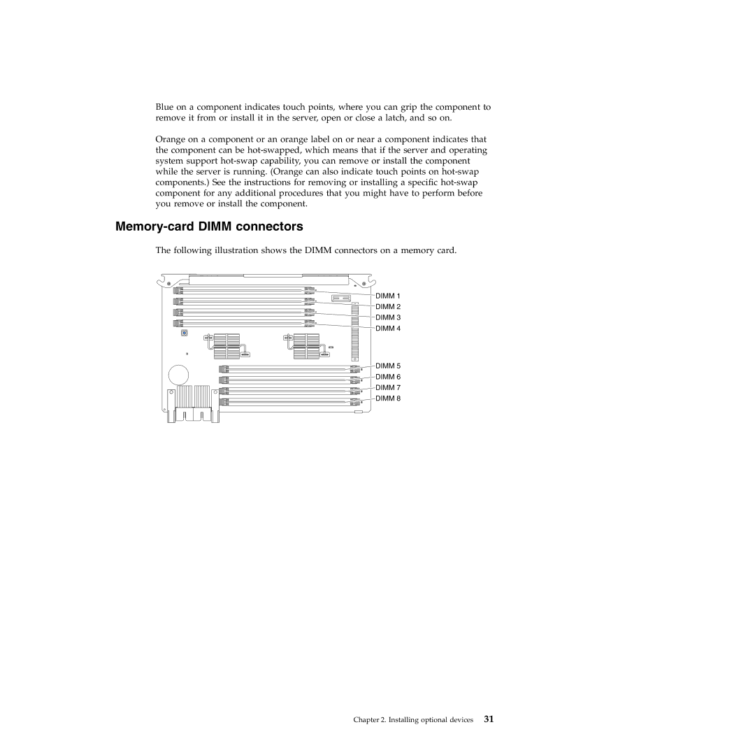
Memory-card DIMM connectors

The following illustration shows the DIMM connectors on a memory card.

DIMM 1

DIMM 2

DIMM 3

DIMM 4

DIMM 5

DIMM 6

DIMM 7

DIMM 8

Chapter 2. Installing optional devices 31

Page 45
Image 45
IBM 71453RU manual Memory-card Dimm connectors