3.Reconnect the cables and power cords (see “Connecting the memory expansion module cables” on page 92).
4.Slide the memory expansion module and the server back into the rack, if necessary.
5.Turn on the peripheral devices and the host server
Replacing the memory expansion module system-board tray
To confirm that the memory expansion module supports the
To replace the
1.Read “Safety” on page v and “Installation guidelines” on page 38.
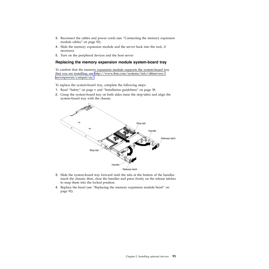
2.Grasp the
Handle
Release latch
![]()
Handle
Release latch
3.Slide the
4.Replace the bezel (see “Replacing the memory expansion module bezel” on page 92).