2.If the server is in a rack, at the back of the server, pull back the
3.If you are installing a
4.Touch the
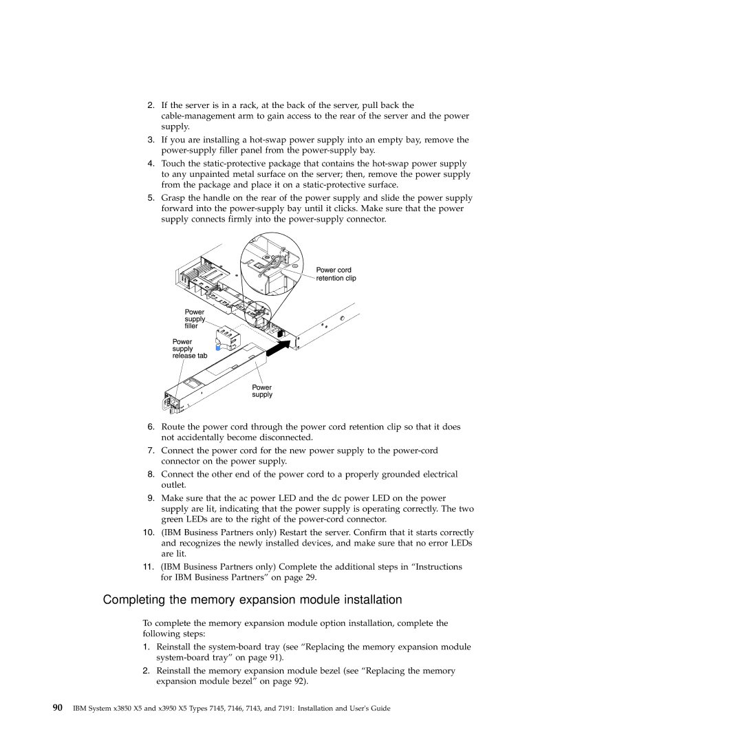
5.Grasp the handle on the rear of the power supply and slide the power supply forward into the
6.Route the power cord through the power cord retention clip so that it does not accidentally become disconnected.
7.Connect the power cord for the new power supply to the
8.Connect the other end of the power cord to a properly grounded electrical outlet.
9.Make sure that the ac power LED and the dc power LED on the power supply are lit, indicating that the power supply is operating correctly. The two green LEDs are to the right of the
10.(IBM Business Partners only) Restart the server. Confirm that it starts correctly and recognizes the newly installed devices, and make sure that no error LEDs are lit.
11.(IBM Business Partners only) Complete the additional steps in “Instructions for IBM Business Partners” on page 29.
Completing the memory expansion module installation
To complete the memory expansion module option installation, complete the following steps:
1.Reinstall the
2.Reinstall the memory expansion module bezel (see “Replacing the memory expansion module bezel” on page 92).
90IBM System x3850 X5 and x3950 X5 Types 7145, 7146, 7143, and 7191: Installation and User's Guide