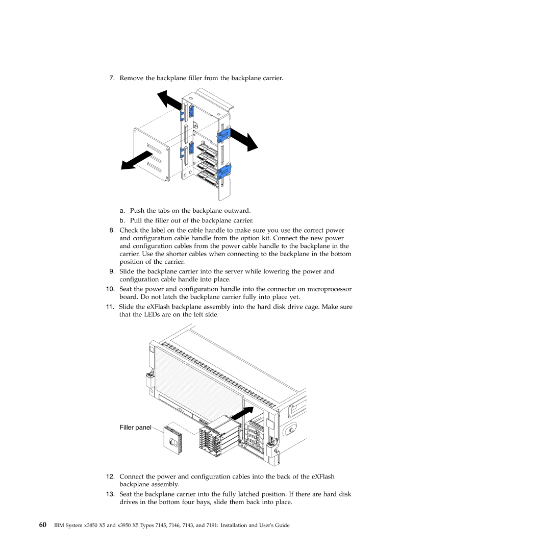
7.Remove the backplane filler from the backplane carrier.
a.Push the tabs on the backplane outward.
b.Pull the filler out of the backplane carrier.
8.Check the label on the cable handle to make sure you use the correct power and configuration cable handle from the option kit. Connect the new power and configuration cables from the power cable handle to the backplane in the carrier. Use the shorter cables when connecting to the backplane in the bottom position of the carrier.
9.Slide the backplane carrier into the server while lowering the power and configuration cable handle into place.
10.Seat the power and configuration handle into the connector on microprocessor board. Do not latch the backplane carrier fully into place yet.
11.Slide the eXFlash backplane assembly into the hard disk drive cage. Make sure that the LEDs are on the left side.
Filler panel
12.Connect the power and configuration cables into the back of the eXFlash backplane assembly.
13.Seat the backplane carrier into the fully latched position. If there are hard disk drives in the bottom four bays, slide them back into place.
60IBM System x3850 X5 and x3950 X5 Types 7145, 7146, 7143, and 7191: Installation and User's Guide
