Note: To change the startup sequence, start the Setup utility and select Start Options from the main menu. See “Using the Setup utility” on page 96 for details about using the Setup utility.
vThe PCI Express 2.0 bus configuration is as follows:
–Expansion slot 1 is x16, slot 2 is x8 (x4 lanes), and slots 3 through 6 are x8.
–Expansion slot 7 is a
–Expansion slots 1 through 4 are
–Expansion slots 5 through 7 are
Attention: Static electricity that is released to internal server components when the server is powered on might cause the server to halt, which might result in the loss of data. To avoid this potential problem, always use an
To install a PCI Express adapter, complete the following steps.
1.Read “Safety” on page v and “Installation guidelines” on page 38.
2.Turn off the server and peripheral devices, and disconnect the power cords and all external cables.
3.Remove the server cover (see “Removing the top cover” on page 44) and determine which PCI Express expansion slot you will use for the adapter.
4.See the documentation that comes with the adapter for instructions for setting jumpers or switches and for cabling.
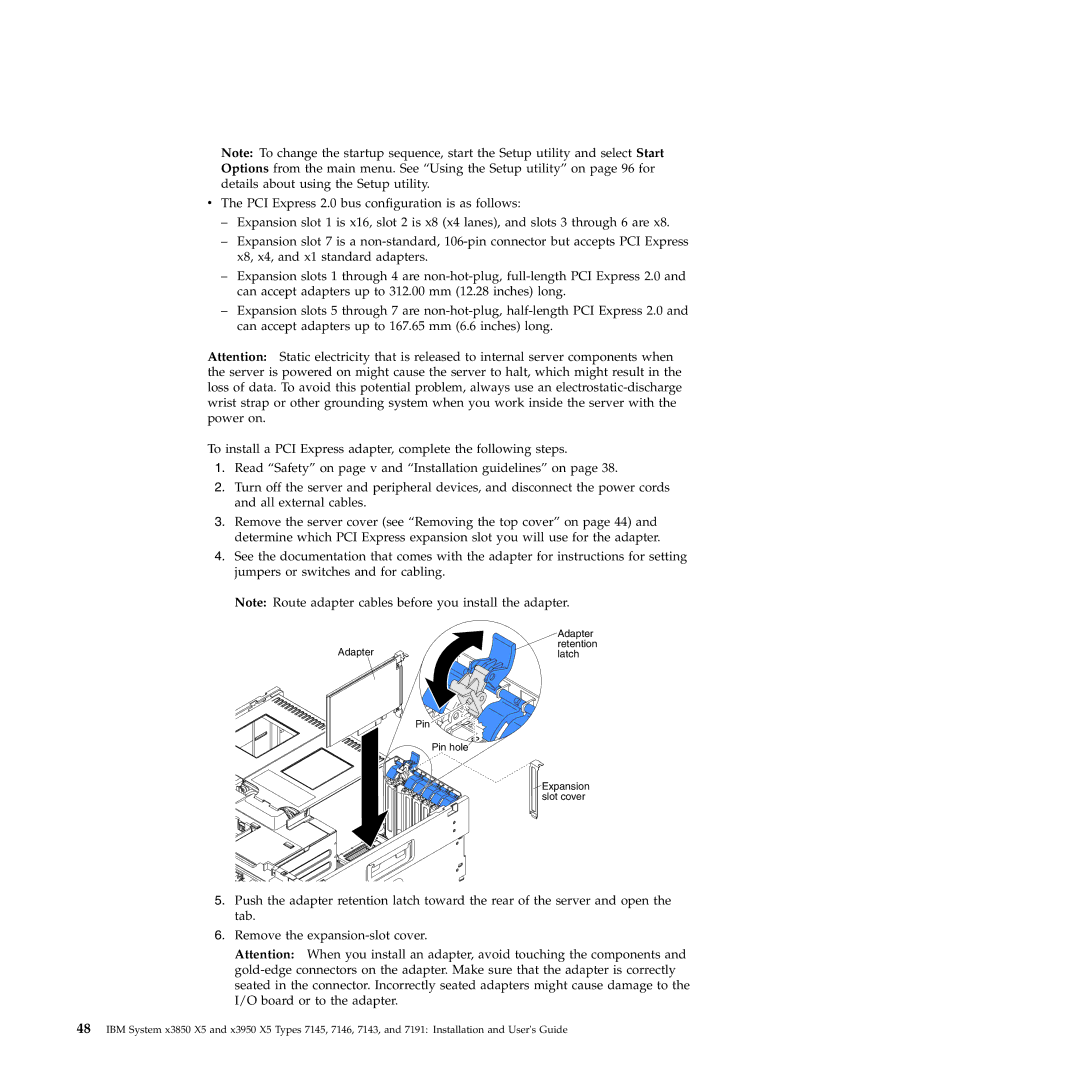
Note: Route adapter cables before you install the adapter.
| Adapter |
Adapter | retention |
latch |
Pin
Pin hole
![]() Expansion slot cover
Expansion slot cover
5.Push the adapter retention latch toward the rear of the server and open the tab.
6.Remove the
Attention: When you install an adapter, avoid touching the components and
48IBM System x3850 X5 and x3950 X5 Types 7145, 7146, 7143, and 7191: Installation and User's Guide