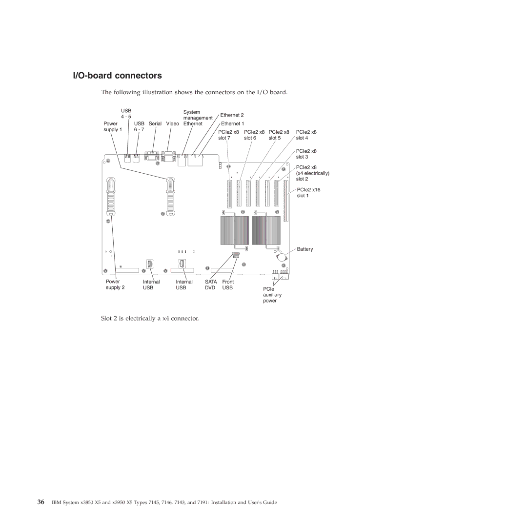
I/O-board connectors
The following illustration shows the connectors on the I/O board.
USB | System | Ethernet 2 |
|
|
|
4 - 5 | management |
|
|
| |
|
|
|
| ||
Power | USB Serial Video Ethernet | Ethernet 1 |
|
| |
supply 1 | 6 - 7 | PCIe2 x8 | PCIe2 x8 | PCIe2 x8 | PCIe2 x8 |
|
| ||||
|
| slot 7 | slot 6 | slot 5 | slot 4 |
PCIe2 x8 slot 3
PCIe2 x8
(x4 electrically) slot 2
PCIe2 x16 slot 1
![]() Battery
Battery
Power | Internal | Internal | SATA | Front |
|
supply 2 | USB | USB | DVD | USB | PCIe |
|
|
|
|
| auxiliary |
|
|
|
|
| power |
Slot 2 is electrically a x4 connector.
36IBM System x3850 X5 and x3950 X5 Types 7145, 7146, 7143, and 7191: Installation and User's Guide
