vWhen you restart the server after you add or remove a DIMM, the server displays a message that the memory configuration has changed.
vMemory cards in connectors 1 and 2 support microprocessor 1, memory cards in connectors 3 and 4 support microprocessor 2, memory cards in connectors 5 and 6 support microprocessor 3, and memory cards in connectors 7 and 8 support microprocessor 4.
vThere are four memory power buses, which are split among the eight memory cards.
vPopulate the
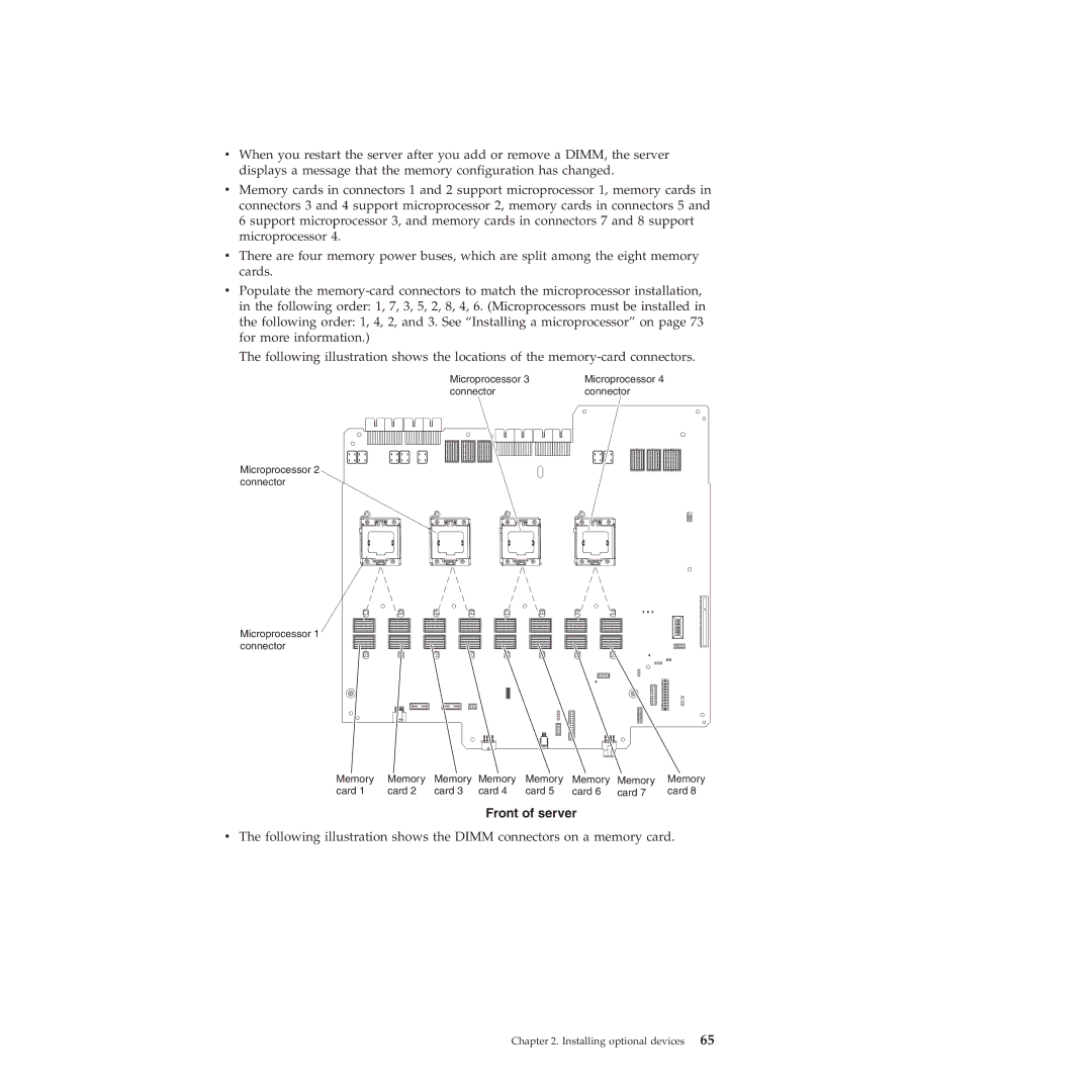
The following illustration shows the locations of the
Microprocessor 3 | Microprocessor 4 |
connector | connector |
Microprocessor 2 connector
Microprocessor 1 connector
Memory | Memory | Memory | Memory | Memory | Memory | Memory | Memory |
card 1 | card 2 | card 3 | card 4 | card 5 | card 6 | card 7 | card 8 |
Front of server
vThe following illustration shows the DIMM connectors on a memory card.