IBM
Page
IBM
Page
Important safety information
About this manual
Online support
IBM online addresses
Contents
Parts listing
General checkout
If the System is not Part of a Cluster
General information
Features and specifications
Server features
Acoustical noise emissions
Environment
Heat output
Reliability, availability, and serviceability
Server controls and indicators
General information
Starting the server
Turning off the server
Hardware Maintenance Manual xSeries
Diagnostic tools overview
Post beep codes, error messages, and error logs
Diagnostic programs and error messages
Error symptoms
Post error messages
Post error log
Post beep codes
Small computer system interface messages
Scsi Messages Description
Diagnostic programs and error messages
Action
Starting the diagnostic programs
Text messages
Diagnostic error messages
Viewing the test log
Power checkout
Recovering Bios
Identifying problems using status LEDs
Diagnostic LEDs
Front panel and system board LEDs
Replacing the battery
Temperature checkout
Diagnosing errors
Troubleshooting the Ethernet controller
Ethernet troubleshooting chart
Ethernet controller Suggested Action Problem
Ethernet controller messages
Message Description
NetWare driver messages for the Ethernet controller
Networks Adapters
Error code Description Hex
Select Properties Advanced
Ethernet teaming messages
Event ID Type Description
Action None
Explanation Team nn. Primary adapter does not sense
Using the Configuration/Setup Utility program
Choices available from the Configuration/Setup main menu
Starting the Configuration/Setup Utility program
System Summary
Power-on Password
Administrator Password
System Information
Product Data
Advanced Setup
Processor Serial Number Access
Memory Settings
System Partition Visibility
Using passwords
Administrator password
Type of password Results
Using the SCSISelect utility program
Starting the SCSISelect utility program
Hardware Maintenance Manual xSeries
Choices available from the SCSISelect menu
Starting the PXE boot agent utility program
Choices available from the PXE boot agent menu
Network Boot Protocol
Boot Order
Setup time wait menu
Legacy OS wake up support
Hardware Maintenance Manual xSeries
Use safe practices when lifting
Tower-to-rack conversion
Removing the left-side cover
Removing the support bracket assembly
Removing the front door and bezel assembly
Rotating the front feet
Relocating the power-switch and LED panel
Installing the top cover
Removing the right-side cover
Removing the hot-swap drive bay filler panel from the bezel
Installing the new system bezel
Attaching the rack-support wheels
Hardware Maintenance Manual xSeries
Installing options
Major components of the xSeries 220 server
System board internal cable connectors
System board options connectors
System board
Dasd I 2C
System board external port connectors
System board jumpers and switches
System board switch block
System board jumper blocks
Before you begin
Switch number Switch description
System reliability considerations
Rotating the stabilizing feet
Removing the side cover
Removing the bezel
Removing the support bracket assembly
Hardware Maintenance Manual xSeries
Working with adapters
Adapter considerations
Installing an adapter
Hardware Maintenance Manual xSeries
Installing internal drives
Internal drive bays
Bay Bay4
Preinstallation steps all bays
Installing a drive in bay 1, 2, 3, or
Hardware Maintenance Manual xSeries
Installing a non-hot-swap hard disk drive in bay 5, 6, or
Installing a hot-swap hard disk drive in bay 5, 6, or
Installing options
Hardware Maintenance Manual xSeries
If you have other options to install or remove, do so now
Installing memory modules
Installing and removing a microprocessor
Installing a microprocessor
Installing options
Hardware Maintenance Manual xSeries
VRM
Removing a microprocessor
Installing the bezel
Installing the cover
Connecting external options
Installation procedure
Connector locations
Input/Output ports
Parallel port
Viewing or changing the port assignments
Pin SPP/ECP Signal EPP Signal
Serial ports
Pin Signal
Universal Serial Bus ports
Keyboard port
USB cables and hubs
Auxiliary-device pointing device port
Video port
Scsi port
Scsi cabling requirements
Scsi connector pin-number assignments
Configuring the Ethernet controller
Ethernet port
Hardware Maintenance Manual xSeries
Installing options
Ethernet port connector
Button kit
Before you begin
Hot-swap hard disk drive cage
Hot-swap backplane
Power supply
Rear fan
Rear Fan Rubber extensions
CD-ROM drive
Floppy disk drive
Bezel release latch
Top/side cover
Handle assembly
Adapter retainer
FRU information service only
Hardware Maintenance Manual xSeries
Beep symptoms
Beep/Symptom FRU/Action
Battery
Beeps Description
Beep/Symptom FRU/Action System Board
Jumper on J28
Optional processor if installed
No beep symptoms
Diagnostic error codes
Error Code/Symptom FRU/Action XXX-S99
Power Supply
XXX-999 Multiple See error text for failing DIMMs
Adapter
Error symptoms
Monitor problems general
CD-ROM drive cable is not
Bypasses the diskette drive
Or the diskette drive does Not work
Post error codes
Setup Action
TechConnect CD Action
Diskette Factory CD Action
Error Code/Symptom FRU/Action 062
Run Configuration/Setup
151 Run Diagnostics
161 Run Configuration/Setup
Error Code/Symptom FRU/Action 185 Run Configuration/Setup
186 Run Configuration/Setup
187 Set serial number in Setup
188 Run Configuration/Setup
1962 Verify a bootable operating system is installed
2400 Video Adapter if installed
5962 Run Configuration/Setup
Update Bios
Error Code/Symptom FRU/Action 00019701
00180100 Run Configuration/Setup
00180200 Run Configuration/Setup
00180300 Run Configuration/Setup
Processor board LEDs
Undetermined problems
ServeRAID
Symptom-to-FRU index
Hardware Maintenance Manual xSeries
Parts listing
System
Tower to Rack Conversion KIT
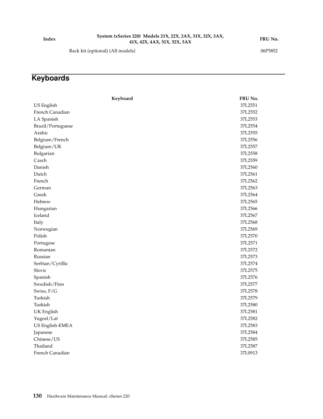
Keyboards
Keyboard FRU No
Power cords
Power cord FRU No
Hardware Maintenance Manual xSeries
Safety information
General safety
Electrical safety
Safety inspection guide
Handling electrostatic discharge-sensitive devices
Safety notices multi-lingual translations
Grounding requirements
Do not
To Connect To Disconnect
≥ 18 kg 37 lbs ≥ 32 kg 70.5 lbs ≥ 55 kg 121.2 lbs
Importante
Para Conectar Para Desconectar
Cuidado
Ao levantar a máquina, faça-o com segurança Instrução
Related service information
Hardware Maintenance Manual xSeries
Related service information
Hardware Maintenance Manual xSeries
Related service information
Hardware Maintenance Manual xSeries
Related service information
Hardware Maintenance Manual xSeries
Connexion Déconnexion
Hardware Maintenance Manual xSeries
Faites-vous aider pour soulever ce produit
Wichtig
Kabel anschlie β en Kabel lösen
Achtung
≥ 18 kg ≥ 32 kg
Pericolo
Per collegare Per scollegare
Attenzione
≥ 18 kg ≥ 32 kg
Hardware Maintenance Manual xSeries
Related service information
Hardware Maintenance Manual xSeries
Peligro
Para la conexin Para la desconexiín
Precaución
≥ 18 kg 37 libras ≥ 32 kg 70,5 libras ≥ 55 kg 121,2 libras
Hardware Maintenance Manual xSeries
Send us your comments
Thank you for your response
Problem determination tips
Trademarks
IBM
Hardware Maintenance Manual xSeries
Page
0406P1822
