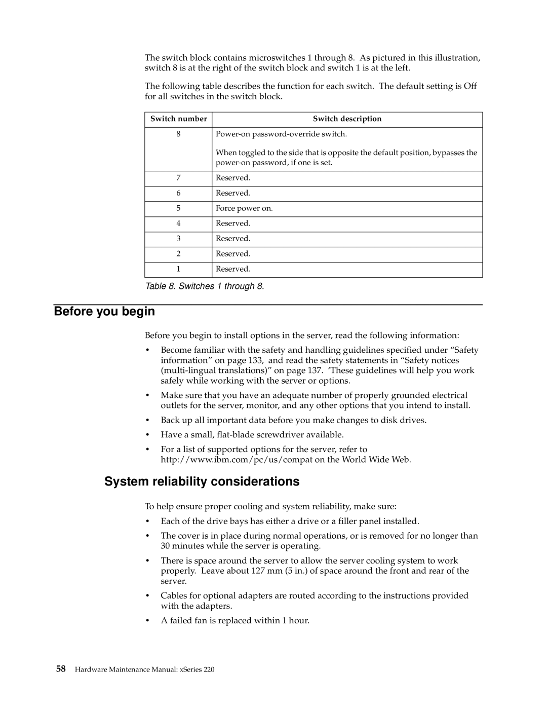
The switch block contains microswitches 1 through 8. As pictured in this illustration, switch 8 is at the right of the switch block and switch 1 is at the left.
The following table describes the function for each switch. The default setting is Off for all switches in the switch block.
Switch number | Switch description |
|
|
8 | |
| When toggled to the side that is opposite the default position, bypasses the |
| |
|
|
7 | Reserved. |
|
|
6 | Reserved. |
|
|
5 | Force power on. |
|
|
4 | Reserved. |
|
|
3 | Reserved. |
|
|
2 | Reserved. |
|
|
1 | Reserved. |
|
|
Table 8. Switches 1 through 8.
Before you begin
Before you begin to install options in the server, read the following information:
•Become familiar with the safety and handling guidelines specified under “Safety information” on page 133, and read the safety statements in “Safety notices
•Make sure that you have an adequate number of properly grounded electrical outlets for the server, monitor, and any other options that you intend to install.
•Back up all important data before you make changes to disk drives.
•Have a small,
•For a list of supported options for the server, refer to http://www.ibm.com/pc/us/compat on the World Wide Web.
System reliability considerations
To help ensure proper cooling and system reliability, make sure:
•Each of the drive bays has either a drive or a filler panel installed.
•The cover is in place during normal operations, or is removed for no longer than 30 minutes while the server is operating.
•There is space around the server to allow the server cooling system to work properly. Leave about 127 mm (5 in.) of space around the front and rear of the server.
•Cables for optional adapters are routed according to the instructions provided with the adapters.
•A failed fan is replaced within 1 hour.