Installation and Preparation
System Connection (When Connecting 16 Cameras)
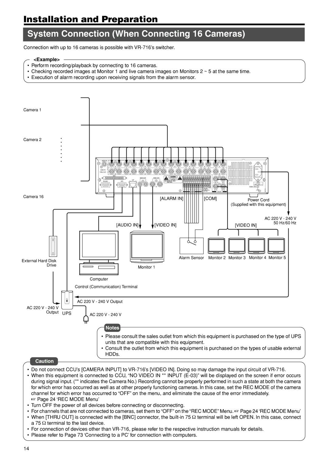
Connection with up to 16 cameras is possible with
<Example>
•Perform recording/playback by connecting to 16 cameras.
•Checking recorded images at Monitor 1 and live camera images on Monitors 2 ~ 5 at the same time.
•Execution of alarm recording upon receiving signals from the alarm sensor.
Camera 1
Camera 2
• • • •
• |
|
|
|
|
|
|
|
|
|
|
|
|
|
|
|
|
|
|
|
|
|
|
|
|
|
|
• |
|
|
|
|
|
|
|
|
|
|
|
|
|
|
|
|
|
|
|
|
|
|
|
|
|
|
• | AUDIO IN |
|
|
|
|
|
|
|
|
|
|
|
|
|
|
|
|
|
|
|
|
|
|
|
|
|
| 1 | 2 | 3 | 4 | 5 | 6 | 7 | 8 | 9 | 10 | 11 |
|
|
| 12 |
|
| 13 |
| 14 | 15 | 16 |
|
| ||
| VIDEO IN |
|
|
|
|
|
|
|
|
|
|
|
|
|
|
|
|
|
|
|
|
|
|
|
|
|
| THRU OUT |
|
|
|
|
|
|
|
|
|
|
|
|
|
|
|
|
|
|
|
|
|
|
|
|
|
|
| SCSI |
|
|
|
|
|
| CAUTION |
|
|
|
|
|
|
|
|
|
|
|
|
|
|
|
|
|
|
|
|
|
| AUDIO OUT | VIDEO OUT |
|
|
|
|
|
|
|
|
|
|
|
|
|
|
|
|
|
| ||
|
|
|
|
|
| RISK OF ELECTRIC SHOCK |
|
|
|
|
|
|
|
|
|
|
|
|
|
|
|
|
| |||
|
|
|
| LAN |
|
|
|
| DO NOT OPEN |
|
|
|
|
|
|
|
|
|
|
|
|
|
|
|
|
|
|
| UPS | 1 | 2 | 1 | 2 | AVIS:RISQUE DE CHOC |
|
|
|
|
|
|
|
|
|
|
|
|
|
|
|
|
| ||
|
|
|
|
|
|
| ELECTRIQ |
|
|
|
|
|
|
|
|
|
| 1 | 4/ | 16 | 5 | 8 | AC IN |
| ||
|
|
|
|
|
|
|
|
|
|
|
|
|
|
|
|
|
|
|
| |||||||
|
|
|
|
|
|
|
|
|
|
|
|
|
|
|
|
|
|
|
|
|
|
|
|
| ) | |
|
|
|
|
|
|
|
|
|
| 1 | 3 | 5 | 7 | 9 | 11 | 13 | 15 | RST | COM IN IN | EXT REC |
|
|
|
| SIGNAL GND |
|
|
|
|
|
|
|
|
|
|
|
|
|
|
|
|
| |||||||||||
|
|
|
|
|
|
|
|
|
| 2 | 4 | 6 | 8 | 10 | 12 | 14 | 16 | OUT | CLK SER |
| 9 | 12 | 13 | 16 |
|
|
|
|
|
|
|
|
|
|
|
| WAR RST REC | COM |
|
| |||||||||||||
|
|
|
|
|
|
|
|
|
|
|
|
|
| ALARM |
|
|
| OUT OUT OUT |
|
| EE OUT |
|
|
| ||
Camera 16 |
|
|
|
|
|
|
| [ALARM IN] |
|
|
|
|
|
|
|
| [COM] |
|
| Power Cord | ||||||
|
|
|
|
|
|
|
|
|
|
|
|
|
|
|
|
|
| |||||||||
|
|
|
|
|
|
|
|
|
|
|
|
|
|
|
|
|
|
|
|
|
|
|
|
| ||
|
|
|
|
|
|
|
|
|
|
|
|
|
|
|
|
|
|
|
|
|
|
|
|
| (Supplied with this equipment) | |
|
|
|
|
|
|
|
|
|
|
|
|
|
|
|
|
|
|
|
|
|
|
|
|
|
| AC 220 V - 240 V |
|
| [AUDIO IN] |
|
| [VIDEO IN] |
|
|
|
|
|
|
|
|
|
|
|
|
|
|
| [VIDEO IN] | 50 Hz/60 Hz | ||||
|
|
|
|
|
|
|
|
|
|
|
|
|
|
|
|
|
|
|
| |||||||
Alarm Sensor Monitor 2 Monitor 3 Monitor 4 Monitor 5
External Hard Disk |
|
|
|
|
|
|
|
|
|
|
|
|
|
|
Drive |
|
|
|
|
|
|
|
|
|
|
|
|
| Monitor 1 |
|
|
|
|
|
|
|
|
|
|
|
|
|
|
|
|
|
|
|
|
|
|
|
|
|
|
|
|
|
|
|
|
|
|
|
| Computer | ||||||||
| Control (Communication) Terminal | |||||||||||||
| AC 220 V - 240 V Output | |||||||||||||
AC 220 V - 240 V |
|
|
|
|
|
|
|
|
|
|
|
|
|
|
Output UPS |
|
|
|
|
| AC 220 V - 240 V | ||||||||
Notes
•Please consult the sales outlet from which this equipment is purchased on the type of UPS units that are compatible with this equipment.
•Consult the outlet from which this equipment is purchased on the types of usable external HDDs.
Caution
•Do not connect CCU’s [CAMERA INPUT] to
•When this equipment is connected to CCU, “NO VIDEO IN ** INPUT
☞ Page 24 ‘REC MODE Menu’
•Turn OFF the power of all devices before connecting or disconnecting.
•For channels that are not connected to cameras, set them to “OFF” on the “REC MODE” Menu. ☞ Page 24 ‘REC MODE Menu’
•When [THRU OUT] is connected with the [BNC] connector, the
•For connection of devices other than
•Please refer to Page 73 ‘Connecting to a PC’ for connection with computers.
14