Names and Functions (Rear)
¤ |
|
|
|
|
|
|
|
|
| ⁄ |
|
|
|
|
|
|
|
|
|
|
|
|
|
|
|
| ) |
AUDIO IN |
|
|
|
|
|
|
|
|
|
|
|
|
|
|
|
|
|
|
|
|
|
|
|
|
|
|
|
1 | 2 | 3 | 4 |
| 5 | 6 |
| 7 | 8 | 9 | 10 | 11 |
|
| 12 |
|
| 13 |
| 14 | 15 | 16 |
|
| |||
VIDEO IN |
|
|
|
|
|
|
|
|
|
|
|
|
|
|
|
|
|
|
|
|
|
|
|
|
|
|
|
THRU OUT |
|
|
|
|
|
|
|
|
|
|
|
|
|
|
|
|
|
|
|
|
|
|
|
|
|
|
|
SCSI |
|
|
|
|
|
|
|
|
| CAUTION |
|
|
|
|
|
|
|
|
|
|
|
|
|
|
|
|
|
|
|
|
| AUDIO OUT |
|
| VIDEO OUT |
|
|
|
|
|
|
|
|
|
|
|
|
|
|
|
|
|
| ||
|
|
|
|
|
|
| RISK OF ELECTRIC SHOCK |
|
|
|
|
|
|
|
|
|
|
|
|
|
|
|
|
| |||
|
|
| LAN |
|
|
|
|
|
| DO NOT OPEN |
|
|
|
|
|
|
|
|
|
|
|
|
|
|
|
|
|
UPS |
| 1 | 2 |
| 1 | 2 |
| AVIS:RISQUE DE CHOC |
|
|
|
|
|
|
|
|
|
|
|
|
|
|
|
|
| ||
|
|
|
|
|
|
|
|
|
|
|
|
|
|
|
|
|
|
|
|
| |||||||
|
|
|
|
|
|
|
| ELECTRIQ |
|
|
|
|
|
|
|
|
|
| 1 | 4/ | 16 | 5 | 8 | AC IN |
| ||
|
|
|
|
|
|
|
|
|
|
|
|
|
|
|
|
|
|
|
|
| |||||||
|
|
|
|
|
|
|
|
|
|
|
|
|
|
|
|
|
|
|
|
| ) | ||||||
|
|
|
|
|
|
|
|
|
|
|
|
|
|
|
|
|
|
|
|
|
|
|
|
|
| ||
|
|
|
|
|
|
|
|
|
|
| 1 | 3 | 5 | 7 | 9 | 11 | 13 | 15 | RST | COM IN IN | EXT REC |
|
|
|
| SIGNAL GND |
|
|
|
|
|
|
|
|
|
|
|
|
|
|
|
|
|
| |||||||||||
|
|
|
|
|
|
|
|
|
|
| 2 | 4 | 6 | 8 | 10 | 12 | 14 | 16 | OUT | CLK SER |
| 9 | 12 | 13 | 16 |
|
|
|
|
|
|
|
|
|
|
|
|
| WAR RST REC | COM |
|
| |||||||||||||
|
|
|
|
|
|
|
|
|
|
|
|
|
|
| ALARM |
|
|
| OUT OUT OUT |
|
| EE OUT |
|
|
| ||
‹ › | fi |
| fl |
| ‡ |
|
| ° |
| · |
|
|
|
|
|
| ‚ |
|
|
|
| ¡ |
|
|
| ||
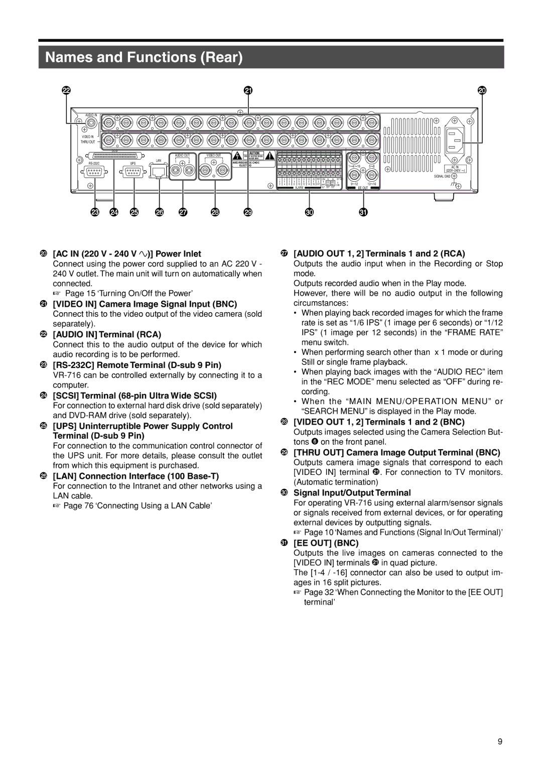
) [AC IN (220 V - 240 V |
| )] Power Inlet |
|
|
|
|
| ‡ [AUDIO OUT 1, 2] Terminals 1 and 2 (RCA) | |||||||||||||||||||
Connect using the power cord supplied to an AC 220 V - 240 V outlet. The main unit will turn on automatically when connected.
☞ Page 15 ‘Turning On/Off the Power’
⁄[VIDEO IN] Camera Image Signal Input (BNC) Connect this to the video output of the video camera (sold separately).
¤[AUDIO IN] Terminal (RCA)
Connect this to the audio output of the device for which audio recording is to be performed.
‹
›[SCSI] Terminal (68-pin Ultra Wide SCSI)
For connection to external hard disk drive (sold separately) and
fi[UPS] Uninterruptible Power Supply Control Terminal
For connection to the communication control connector of the UPS unit. For more details, please consult the outlet from which this equipment is purchased.
fl[LAN] Connection Interface (100 Base-T)
For connection to the Intranet and other networks using a LAN cable.
☞ Page 76 ‘Connecting Using a LAN Cable’
Outputs the audio input when in the Recording or Stop mode.
Outputs recorded audio when in the Play mode. However, there will be no audio output in the following circumstances:
•When playing back recorded images for which the frame rate is set as “1/6 IPS” (1 image per 6 seconds) or “1/12 IPS” (1 image per 12 seconds) in the “FRAME RATE” menu switch.
•When performing search other than x 1 mode or during Still or single frame playback.
•When playing back images with the “AUDIO REC” item in the “REC MODE” menu selected as “OFF” during re- cording.
•When the “MAIN MENU/OPERATION MENU” or “SEARCH MENU” is displayed in the Play mode.
°[VIDEO OUT 1, 2] Terminals 1 and 2 (BNC)
Outputs images selected using the Camera Selection But- tons 6 on the front panel.
·[THRU OUT] Camera Image Output Terminal (BNC) Outputs camera image signals that correspond to each [VIDEO IN] terminal ⁄. For connection to TV monitors. (Automatic termination)
‚Signal Input/Output Terminal
For operating
☞ Page 10 ‘Names and Functions (Signal In/Out Terminal)’
¡[EE OUT] (BNC)
Outputs the live images on cameras connected to the [VIDEO IN] terminals ⁄ in quad picture.
The
☞Page 32 ‘When Connecting the Monitor to the [EE OUT] terminal’
9