2Unpacking to Installation
2.2.4Grounding procedures
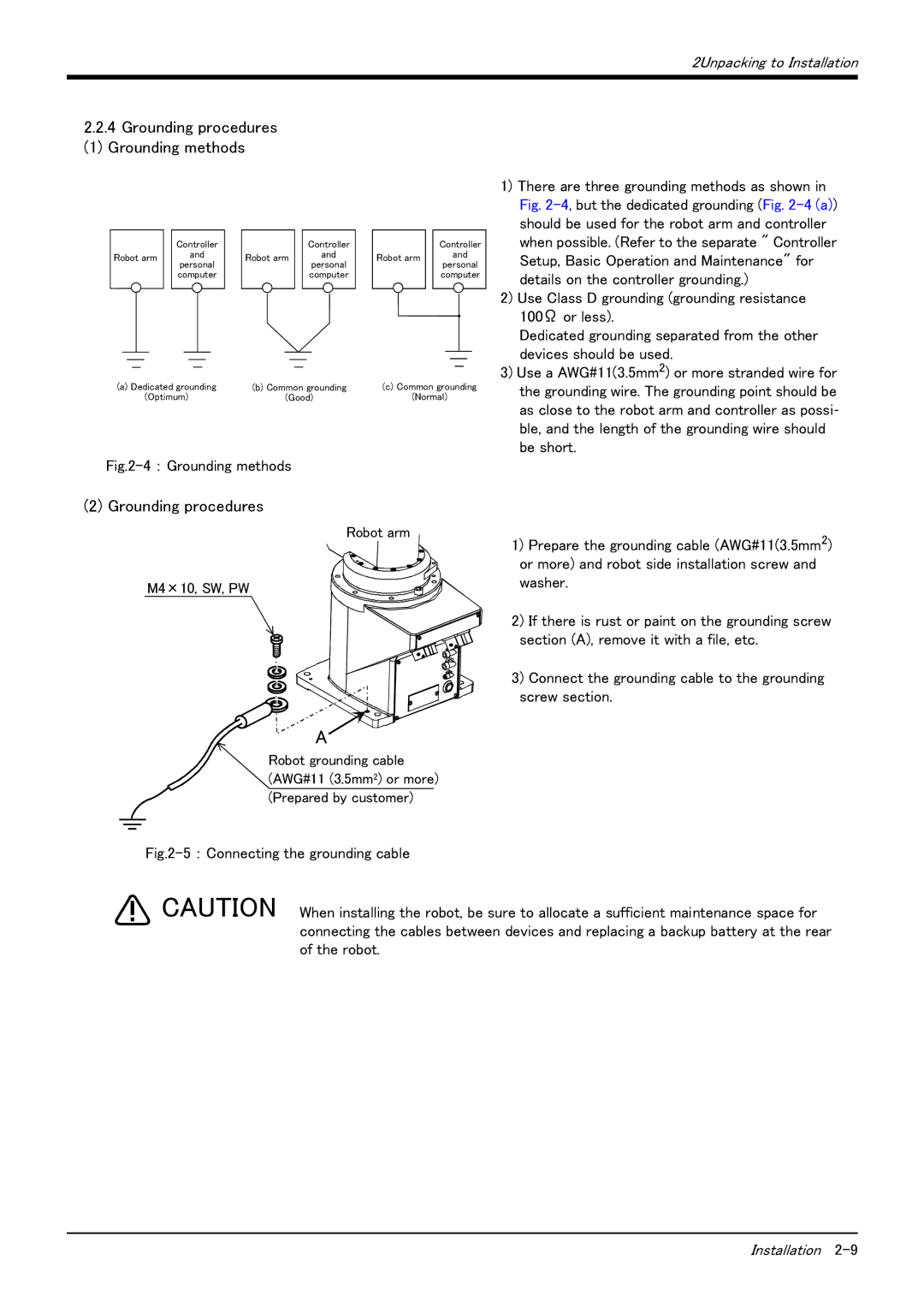
(1) Grounding methods
| Controller |
| Controller |
| Controller | |
Robot arm | and | Robot arm | and | Robot arm | and | |
personal | personal | personal | ||||
|
|
| ||||
| computer |
| computer |
| computer |
(a) Dedicated grounding | (b) Common grounding | (c) Common grounding |
(Optimum) | (Good) | (Normal) |
Fig.2-4 : Grounding methods
1)There are three grounding methods as shown in Fig.
2)Use Class D grounding (grounding resistance 100Ω or less).
Dedicated grounding separated from the other devices should be used.
3)Use a AWG#11(3.5mm2) or more stranded wire for the grounding wire. The grounding point should be as close to the robot arm and controller as possi- ble, and the length of the grounding wire should be short.
(2) Grounding procedures
Robot arm
M4×10, SW, PW
A
Robot grounding cable (AWG#11 (3.5mm2) or more) (Prepared by customer)
Fig.2-5 : Connecting the grounding cable
1)Prepare the grounding cable (AWG#11(3.5mm2) or more) and robot side installation screw and washer.
2)If there is rust or paint on the grounding screw section (A), remove it with a file, etc.
3)Connect the grounding cable to the grounding screw section.
CAUTION When installing the robot, be sure to allocate a sufficient maintenance space for connecting the cables between devices and replacing a backup battery at the rear of the robot.
Installation