2Unpacking to Installation
2.2.3 Installation procedures
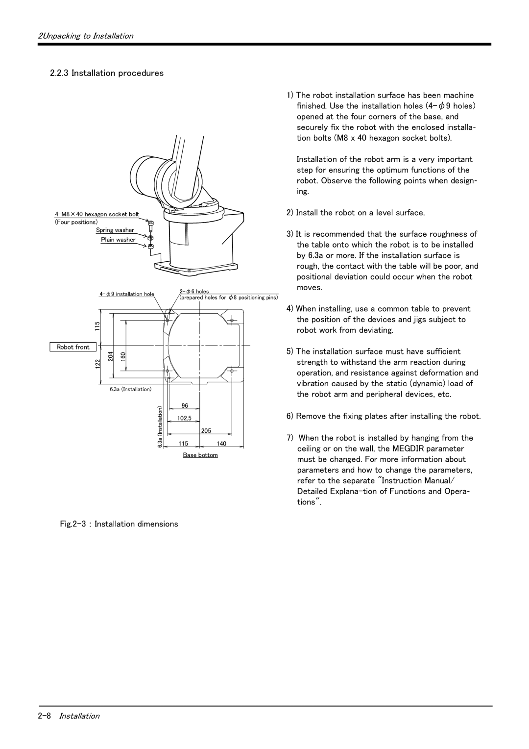
Spring washer Plain washer
(prepared holes for φ8 positioning pins) | ||
|
115 |
|
|
Robot front |
|
|
122 | 204 | 160 |
6.3a (Installation)
(Installation) | 96 |
|
102.5 |
| |
6.3a |
| 205 |
115 | 140 |
Base bottom
Fig.2-3 : Installation dimensions
1)The robot installation surface has been machine finished. Use the installation holes (4-φ9 holes) opened at the four corners of the base, and securely fix the robot with the enclosed installa- tion bolts (M8 x 40 hexagon socket bolts).
Installation of the robot arm is a very important step for ensuring the optimum functions of the robot. Observe the following points when design- ing.
2)Install the robot on a level surface.
3)It is recommended that the surface roughness of the table onto which the robot is to be installed by 6.3a or more. If the installation surface is rough, the contact with the table will be poor, and positional deviation could occur when the robot moves.
4)When installing, use a common table to prevent the position of the devices and jigs subject to robot work from deviating.
5)The installation surface must have sufficient strength to withstand the arm reaction during operation, and resistance against deformation and vibration caused by the static (dynamic) load of the robot arm and peripheral devices, etc.
6)Remove the fixing plates after installing the robot.
7)When the robot is installed by hanging from the ceiling or on the wall, the MEGDIR parameter must be changed. For more information about parameters and how to change the parameters, refer to the separate "Instruction Manual/ Detailed