4.Supplemental note for the installation surface receiving force
Supplemental details
Magnitude of each reaction force added to
Table
FV
MT
Spring washer |
|
|
|
|
Plain washer |
|
| M | L |
F |
|
| ||
| H |
| F | |
|
|
| ||
|
|
|
| |
|
|
|
| H |
| F |
| M | |
| H |
| L | |
|
|
|
| |
| F | |
| H | |
| F | |
| V | |
(prepared holes for φ8 positioning pins) | ||
|
115
Robot front
122 | 204 | 160 |
6.3a (Installation)
6.3a (Installation)
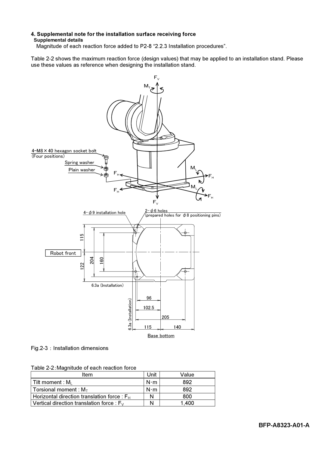
Fig.2-3:Installation dimensions
96
102.5
205
115140
Base bottom
Table
Item | Unit | Value |
Tilt moment : ML | N・m | 892 |
Torsional moment : MT | N・m | 892 |
Horizontal direction translation force : FH | N | 800 |
Vertical direction translation force : FV | N | 1,400 |