2Unpacking to Installation
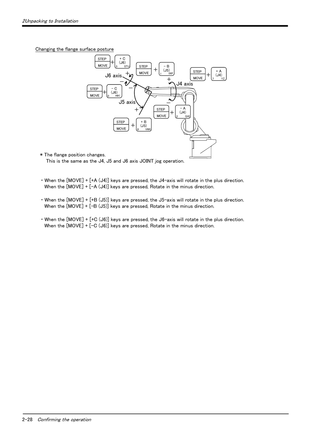
Changing the flange surface posture
STEP | + | + C |
|
|
| |
MOVE | (J6) |
|
| STEP | ||
5 | STU |
|
| |||
| J6 axis + |
|
| MOVE | ||
|
|
|
| |||
|
|
| - |
|
|
|
STEP | + | - C | - |
|
| |
MOVE | (J6) |
|
|
|
| |
0 | ABC |
|
|
| ||
|
|
| J5 axis |
|
| |
|
|
|
| + |
| |
|
| STEP | + |
| + B | |
|
| MOVE |
| (J5) | ||
|
|
| 6 | VWX | ||
+ | - B |
|
|
| |
(J5) |
| STEP | + A | ||
| 1 | DEF |
| ||
|
|
| + (J4) | ||
|
| + |
| MOVE | |
|
|
| 7 YZ_ | ||
|
| J4 axis |
| ||
| - |
|
|
| |
STEP |
| - A |
|
| |
+ (J4) |
|
| |||
MOVE |
| 2 GHI |
|
| |
|
|
|
|
|
|
* The flange position changes.
This is the same as the J4, J5 and J6 axis JOINT jog operation.
・ When the [MOVE] + [+A (J4)] keys are pressed, the
・ When the [MOVE] + [+B (J5)] keys are pressed, the
・ When the [MOVE] + [+C (J6)] keys are pressed, the
