Mitsubishi Electronics RV-6S instruction manual No.2 arm View from No arm cover B side

Models: RV-6S

1 78
Download 78 pages 11.72 Kb
Page 42
Image 42

3Installing the option devices

Fig. 3-1and Fig. 3-2shows the solenoid valve installation procedures and the solenoid valve connector connection procedures. The installation procedures are as follow. This work must be carried out with the controller power turned OFF.

1)Remove the hexagon socket bolts (five M4 x 10) and truss screw (three M3 x 8) that hold the No. 2 arm cover B <2>, and then remove both the No. 2 arm cover B <2>.

2)Remove the socket bolts <4> (four M4 x 8) that hold the No. 2 arm cover C <3>, and then remove both the No. 2 arm cover C <3>.

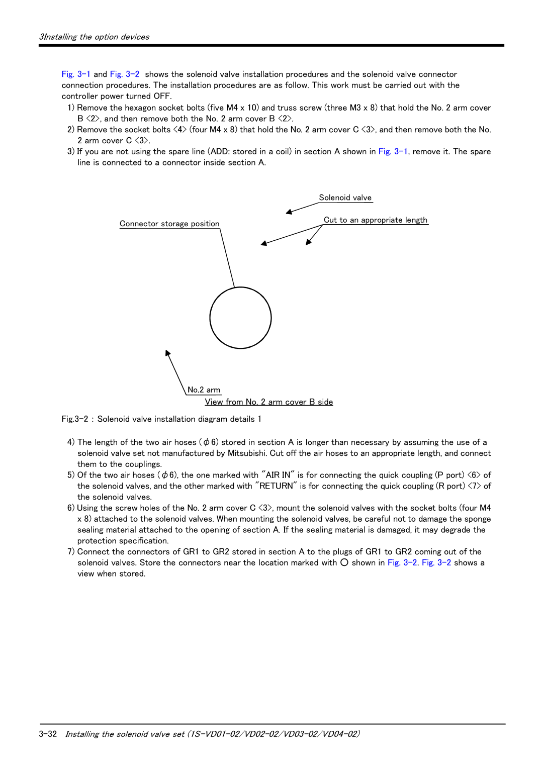
3)If you are not using the spare line (ADD: stored in a coil) in section A shown in Fig. 3-1, remove it. The spare line is connected to a connector inside section A.

Solenoid valve

Connector storage position

Cut to an appropriate length


No.2 arm

View from No. 2 arm cover B side

Fig.3-2 : Solenoid valve installation diagram details 1

4)The length of the two air hoses (φ6) stored in section A is longer than necessary by assuming the use of a solenoid valve set not manufactured by Mitsubishi. Cut off the air hoses to an appropriate length, and connect them to the couplings.

5)Of the two air hoses (φ6), the one marked with "AIR IN" is for connecting the quick coupling (P port) <6> of the solenoid valves, and the other marked with "RETURN" is for connecting the quick coupling (R port) <7> of the solenoid valves.

6)Using the screw holes of the No. 2 arm cover C <3>, mount the solenoid valves with the socket bolts (four M4 x 8) attached to the solenoid valves. When mounting the solenoid valves, be careful not to damage the sponge sealing material attached to the opening of section A. If the sealing material is damaged, it may degrade the protection specification.

7)Connect the connectors of GR1 to GR2 stored in section A to the plugs of GR1 to GR2 coming out of the solenoid valves. Store the connectors near the location marked with ○ shown in Fig. 3-2. Fig. 3-2shows a view when stored.

3-32Installing the solenoid valve set (1S-VD01-02/VD02-02/VD03-02/VD04-02)

Page 42
Image 42
Mitsubishi Electronics RV-6S instruction manual No.2 arm View from No arm cover B side