NETGEAR 7000 Series Managed Switch Administration Guide Version 7.2
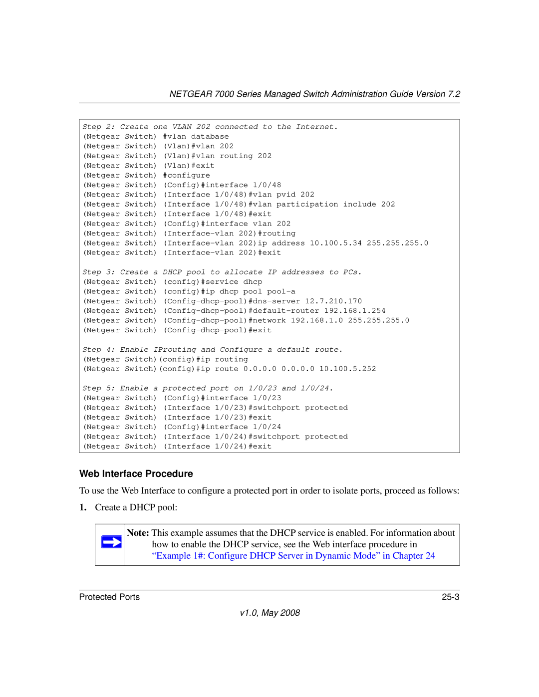
Step 2: Create one VLAN 202 connected to the Internet. (Netgear Switch) #vlan database
(Netgear Switch) (Vlan)#vlan 202 (Netgear Switch) (Vlan)#vlan routing 202 (Netgear Switch) (Vlan)#exit
(Netgear Switch) #configure
(Netgear Switch) (Config)#interface 1/0/48 (Netgear Switch) (Interface 1/0/48)#vlan pvid 202
(Netgear Switch) (Interface 1/0/48)#vlan participation include 202 (Netgear Switch) (Interface 1/0/48)#exit
(Netgear Switch) (Config)#interface vlan 202 (Netgear Switch)
(Netgear Switch)
Step 3: Create a DHCP pool to allocate IP addresses to PCs. (Netgear Switch) (config)#service dhcp
(Netgear Switch) (config)#ip dhcp pool
(Netgear Switch)
Step 4: Enable IProuting and Configure a default route. (Netgear Switch)(config)#ip routing
(Netgear Switch)(config)#ip route 0.0.0.0 0.0.0.0 10.100.5.252
Step 5: Enable a | protected port on 1/0/23 and 1/0/24. |
(Netgear Switch) | (Config)#interface 1/0/23 |
(Netgear Switch) | (Interface 1/0/23)#switchport protected |
(Netgear Switch) | (Interface 1/0/23)#exit |
(Netgear Switch) | (Config)#interface 1/0/24 |
(Netgear Switch) | (Interface 1/0/24)#switchport protected |
(Netgear Switch) | (Interface 1/0/24)#exit |
Web Interface Procedure
To use the Web Interface to configure a protected port in order to isolate ports, proceed as follows:
1.Create a DHCP pool:
Note: This example assumes that the DHCP service is enabled. For information about ![]() how to enable the DHCP service, see the Web interface procedure in
how to enable the DHCP service, see the Web interface procedure in
“Example 1#: Configure DHCP Server in Dynamic Mode” in Chapter 24
Protected Ports |
