NETGEAR 7000 Series Managed Switch Administration Guide Version 7.2
Example #1: Create Two VLANs
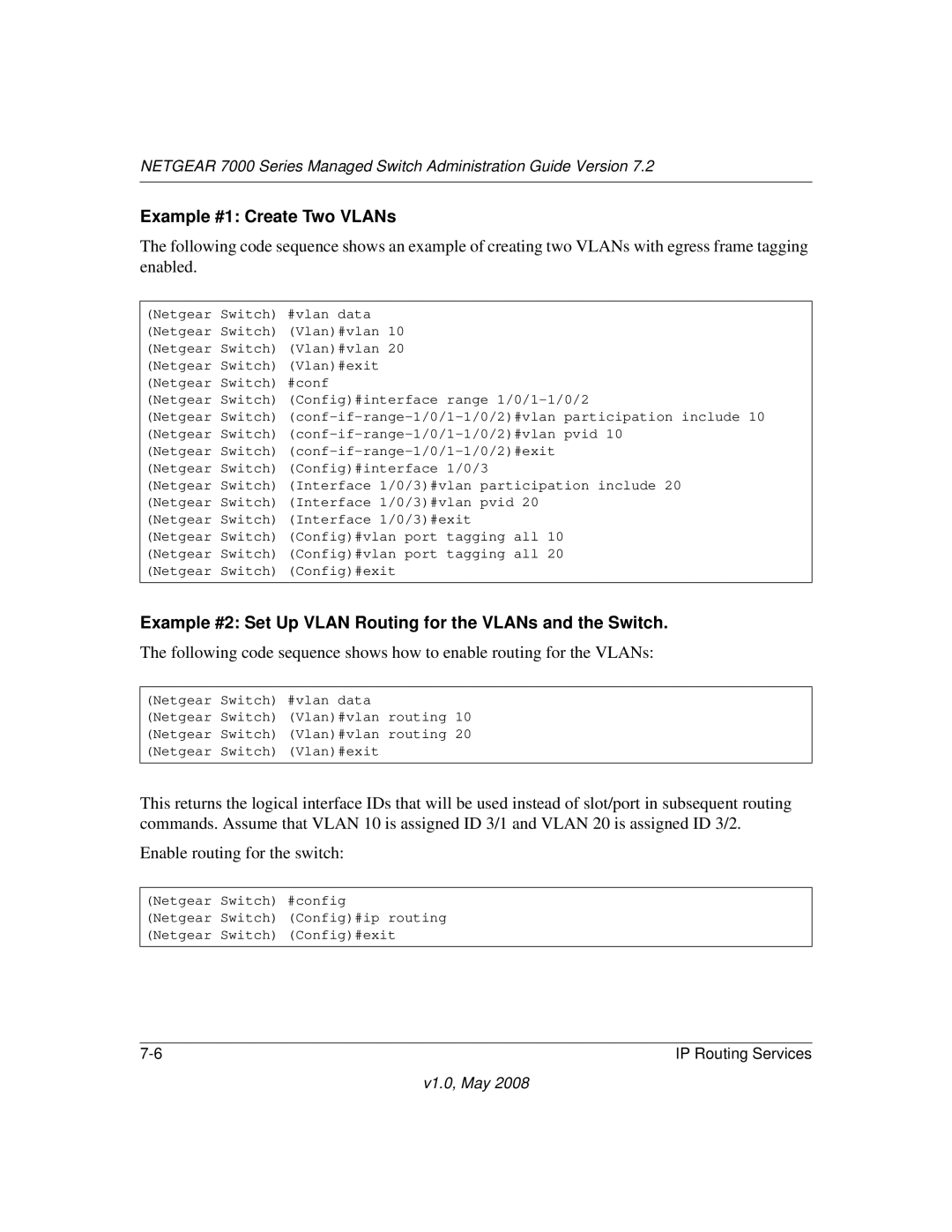
The following code sequence shows an example of creating two VLANs with egress frame tagging enabled.
(Netgear Switch) #vlan data (Netgear Switch) (Vlan)#vlan 10 (Netgear Switch) (Vlan)#vlan 20 (Netgear Switch) (Vlan)#exit (Netgear Switch) #conf
(Netgear Switch) (Config)#interface range
(Netgear Switch)
(Netgear Switch)
(Netgear Switch) (Interface 1/0/3)#vlan participation include 20 (Netgear Switch) (Interface 1/0/3)#vlan pvid 20
(Netgear Switch) (Interface 1/0/3)#exit
(Netgear Switch) (Config)#vlan port tagging all 10 (Netgear Switch) (Config)#vlan port tagging all 20 (Netgear Switch) (Config)#exit
Example #2: Set Up VLAN Routing for the VLANs and the Switch.
The following code sequence shows how to enable routing for the VLANs:
(Netgear Switch) #vlan data
(Netgear Switch) (Vlan)#vlan routing 10 (Netgear Switch) (Vlan)#vlan routing 20 (Netgear Switch) (Vlan)#exit
This returns the logical interface IDs that will be used instead of slot/port in subsequent routing commands. Assume that VLAN 10 is assigned ID 3/1 and VLAN 20 is assigned ID 3/2.
Enable routing for the switch:
(Netgear Switch) #config
(Netgear Switch) (Config)#ip routing (Netgear Switch) (Config)#exit
IP Routing Services |
