Page
Important Safety Instructions
Page
Page
Memory Backup
Power Supply
Placement
Maintenance
Disclaimer of liability
Handling the Internal Hard Disk Drive
Copyright
About the License Agreement
Table of Contents
Table of Contents
Determining Output
Using the Metronome
Input Mixer Default Assignment Channel Link
Fader/Mute Button
Master Block
Procedure for Using Effects
Connecting Insert Effects
Track Mixer
Using EZ Routing Step Editing
Connecting Loop Effects
Using Effects While Recording
Three Important Reminders About Using Effects
Editing Operations
Connecting an external CD-R/CD-RW Drive
Using the Monitor Knob to Adjust Channel Panning
Phrase Editing
Synchronizing with Midi Sequencers
Using Midi Controller Messages
Recovering Drive Space
Using External Hard Drives
Saving Song Data to DAT DAT Backup
Hard Drive Maintenance
Backup Options
CD-R Backup and Recover
Syncing a VS- 1824 and VS-880/880EX or VSR-880
Play and Record Settings
Alarm Clock
Using External Effects Units
About the Package Contents
Main Features
Preparations
Simple Operation
Connectivity
Major Options
Input Knobs
Peak Indicators
Top and Rear Panels
Mixer Section
Phones Knob
Status Buttons
Channel Faders
Top and Rear Panels Monitor Knob
Recorder Section
CD-RW/MASTERING Button
MIDI/DISK Indicator
Transport Control Buttons
Contrast Knob
Rear Panel
Front Panel
Saving and Managing Data
Managing Disk Contents Partitioning
Before You Start VS-1824 Terminology
Location Where a Performance is Recorded Song
Takes and Phrases
Sources, Tracks, and Channels
Erase AutoMix data p
About Events About Button Names
Execute Song Store p
Execute Song Optimize p
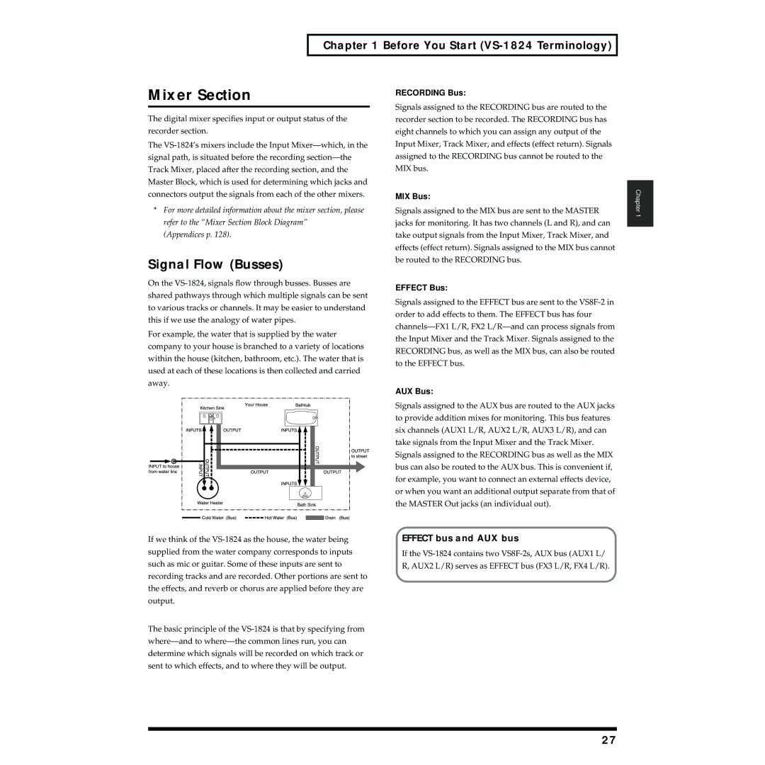
Effect bus and AUX bus
Signal Flow Busses
Channels
Switching the Fader Functions
Input Mixer
Track Mixer
Differences from a Tape-Type MTR
Master Block
Auxiliary Tracks for Each Track
Track Minutes and Recording Time
Insert
Connecting Effects
Effects Section
About the Effect Expansion Board
Basic Operation
Turning the Power On and Off
Turning On the Power
Turning Off the Power
Basic Operation
Saving Your Song Song Store
Restarting
If Store Current ? is Displayed
Time Edit
Setting the Internal Clock
Date Edit
Date Format
Adjusting the display Contrast
Operating the VS-1824
Basic Navigation
Select buttons
Function Buttons
Jump button
Shift button
Mixer and System Initialize
Time / Value dial
Function is called Initialize System/Mixer parameter
Center Part of the Display
Playback Operations
Display
Display Regions
Selecting a Playlist Display
Lower Part of the Display
Playback Operations
Function Buttons While on the Playlist Display
Mixer Channel Display
Muting Inputs and Effect Returns
Changing Track Status
Muting and Soloing
Muting Tracks
Storing Locators
Using Locators
Solo Mode
Quick Soloing
Changing the Locator Bank
Editing Stored Locators
Clearing Locator
About Marker Numbers
Using Markers
Locate to a Marker Using Previous and Next
Storing a Marker
Clearing All Markers
Editing Marker Values
Clearing Markers
Clearing Specific Markers
Other Ways to Move In a Song
Changing Playback Position Using Jump
Change Playback Position Using TIME/VALUE Dial
Move to the Beginning or End of a Song Using FF and REW
Protecting Songs Song Protect
Protecting Performances
About Song Protect
To Remove Song Protect
Selecting and Loading Songs Song Select
Items Necessary for Recording
Recording Operations
Preparing for a New Recording
Create a New Song Song New
Copy System PRM Copy System Parameters
Recording Mode
Recording Operations
Icon
All times are approximate
About Recording Times
Song Numbers
If Drive Busy! is Displayed
Connecting Instruments
Recording and Mixing Process
Input 8 jack and the Guitar Hi-Z jack cannot be
Sources Assigned to Tracks
Recording to the Tracks
When You Are Recording in Stereo
What to do About Low-Level Input Signals
Recording on Other Tracks Overdubbing
Recording Using Different Virtual Tracks V-Tracks
Manual Punch-In Using the Record Button
Manual Punch-In Using the Foot Switch
Manual Punch-In/Punch-Out
GPI
Using Locators
Using Markers
Auto Punch-In and Punch-Out
Recording Procedure When Using Auto Punch
Programming Points During Song Playback
Editing Punch-In and Punch-Out Points
Loop Recording
F4 End
Recording Procedure Using Loop Play
Editing the Loop Points for Punch-In and Punch-Out
F1 Start
Recording and Editing Operation Which Can Be Undone Undo
Undo and Redo
Undo message
To cancel an Undo Redo
Cancel Only the Very Last- Performed Operation
To use the Undo Function
Track Bouncing
Selecting Source Tracks Destination Tracks
Set Meters to Pre-Fader Track
Record the Track Bounce
Track Bouncing With Effects
If Digital In Unlock is Displayed
Recording a Digital Source
Preparations for Recording a Digital Source
If Digital In Lock is Displayed
Sync Gen. Sync Generator
Using the Metronome
Recording From a CD
Turn On the Metronome
Midi
Using an External Midi Sound Source to Play the Metronome
Program the Tempo Map
INT
MIDAcc.Note Accent Note
Midi Thru Midi Thru Switch
Out
Thru
Using the Digital Mixer
Method Two Input Mixer Screen
Method One Switching the Fader Functions FADER/MUTE Button
Using the Digital Mixer
Fader/Mute Button
Monitor Output Connectors
Determining Output
Mon Monitor
DOUT1 Digital OUT
AUX Connectors
Digital Out Connectors
AUX a
DIR OUT Direct OUT
Direct Out Connectors
Fader Mode
Mixer Routing
Sources Assigned to Tracks
Mix Assign Switch
Input Mixer Default Assignment
Adjust the Levels of Linked Channels
Channel Link
Link Adjacent Mixer Channels
Adjusting the Panning of Channel Linked Channels
When VS-1824 is selected on fader mode p
When VS-1880 is selected on fader mode p
Group
Linking the Faders of Two or More Channels Fader Group
Using the Equalizer EQ
Sw Equalizer Switch
Selecting V-Tracks
Mid
Equalizer Select
Band EQ
Low
INV
Phase
Attenuation
NRM
Equalizer
Copying Mixer Settings
When Phase Mismatch is a Problem
When Phase Mismatch is Not a Problem
EZ Routing
Mixer Scenes
Storing a Mixer Scene
Scene
Recalling a Mixer Scene
Deleting a Mixer Scene
Updating a Mixer Scene
Input Mixer
Mixer Channel Strip Detail
F5 AUX AUX Send
F2 FX2 Effect 2 Send
F4 FX4 Effect 4 Send
F3 FX3 Effect 3 Send
F2 FX2In Effect 2 Insert
F1 FX1In Effect 1 Insert
F2 ATT Attenuation
F3 FX3In Effect 3 Insert
F4 FX4In Effect 4 Insert
F1 Link Channel Link
Track Mixer
F1FX1 Effect 1 Send
F5 V.Trk V-Track Select
Sets the channel’s send level 0-127 to the Effect 4 Bus
F2 FX2In Effect 2 Insert
Mute
F4FX4In Effect 4 Insert
F2 Stats Status
Play
F3 AUX.A AUX a
Master Block
F5 DOUT1 Digital OUT
F4 AUX.B AUX B
This connects the effect in the Master Block mixer section
F4 FX4 Effect 4 Master Send
F1 FX1 Effect 1 Master Send
F2 FX2 Effect 2 Master Send
F3 FX3 Effect 3 Master Send
Insert Effects
Using Internal Effects VS8F-2
Effect Types
Location of Effects
Making the Effect Connection
Procedure for Using Effects
Using Internal Effects VS8F-2
Loop Effects
If No Effect Board Appears in the Display
Selecting a Preset Patch
Selecting Effect Patches
101
Save an Effect as a User Patch
Creating and Saving User
Effect Patches
Create a User Effect Patch
103
Connecting Insert Effects
Connecting Insert Effects to Inputs and Tracks
Save an Effect Patch as Part of a Mixer Scene
104
105
Connecting Insert Effects in the Master Block
Next, Set up the Mixer
Three Insert Effect Examples
106
107
Connecting Loop Effects
Adjust the Effect Return Level using the Channel Faders
Effects Return Section
Effects
Two Examples of Using Loop
Listening to an Insert Effect While Recording
Using Effects While Recording
Four Methods of Using Effects While Recording
Next, Set up the Track Mixer
Recording Insert Effects
Summary Using Insert Effects While Recording
Listening to a Loop Effect While
Recording
To Stereo Track 9/10
Recording a loop effect
111
Finally, Assign both Input 1 and Effects Return
Three Important Reminders About Using Effects
Recording Stereo Effects
112
Quick Editing
EZ Routing
113
Step Editing
Using EZ Routing Step Editing
Setting Up for Recording Using Step Editing
114
115
116
Setting Up for Mixing Using Step Editing
117
Setting Up for Bouncing Using Step Editing
118
119
Setting Up for Mastering Using Step Editing
120
121
Using EZ Routing Quick Editing
122
Track Mixer Settings
Deleting an EZ Routing Template
Using EZ Routing Templates
Saving an EZ Routing Template
Recalling an EZ Routing Template
Input Channel/TRACK Channel
Automix
Mixer Automation
124
Realtime Automix of Track Faders
Using Automix
Adjust the Display for Automix
Realtime Automix
126
Realtime Automix of Input Faders
Automating the Master Stereo Mix and Monitor Output
Automating Effect Returns
127
Snapshot Automation
128
Snap Mode
Snap Mode Settings ALL
Automating Effect Changes
When the timeline is positioned at a Snapshot marker
Gradation
129
Example 2 Fade Out at End of Song
Automix Two Gradation Examples
130
Example 1 Crossfade Between Stereo Tracks
131
Updating Automix
Updating Automix for a Selected Group of Faders
Automix Updating Automix for a Section of a Song
132
Editing Automix Data
Editing Automix Data Micro Edit
Erasing Data from a Specific Area Erase
Copying Data to Another Location Copy
133
Target
134
Destination Target
Destination Mark
135
Smooth Data Transitions Gradation
Marker Add
Increasing or Decreasing All Data Values Shift/Expand
136
Gradation Curve
Threshold
137
Shift
Expand
138
Erasing Automix Data
Erasing Automix Data on Specified Channels
Erasing Automix Data on All Channels
139
Track and Phrase Editing
Track Editing
Track Erase
Track Cut
Track and Phrase Editing
140
141
142
Track Move
+Insert
143
From From Point
To To Point
144
Track Copy
Copy Time Copy Time
145
146
Track Insert
147
Track Exchange
148
Track Time Compression/ Expansion
Vocal, Narration Slow-tempo Songs Fast-tempo Songs To Point
Pitch Mode
149
Type
150
Track Name
151
Track Import
Phrase Editing
Phrase Delete
152
Dividing a Phrase Phrase Divide/Split
Automatically Dividing a Phrase Phrase Divide
153
OUT Threshold
Splitting a Phrase into Two Parts Phrase Split
154
Margin
Phrase Move
155
Divide Split To to point
Quantize
156
Phrase Copy
157
Overlap
Copy Time
158
159
Phrase Trim
160
Phrase Trim Out
Take
Phrase New
Creating a New Phrase
161
Naming Takes
Phrase Name
162
163
Deleting a Take
Steps for Track Editing
Using the from Point Effectively
Editing Tips & Tools
Editing Operations
Precision Editing
Set the Edit Points
Quick Editing
Editing Tips & Tools
166
Editing Tips & Tools Setting Edit Points Using Preview
Setting Edit Points Using Scrub
Adjusting the Preview Length
Setting Scrub Direction
Setting Scrub Length
General Guidelines for Using Scrub
Set the TIME/VALUE Dial to Adjust Frame Increments
Summary of Using Scrub
Waveform Display
168
Perform the Button- Pushes to Complete the Edit
Entering Editing Time Values
169
When to Use Phrase Editing
Track Editing vs. Phrase Editing
170
171
Seamless Looping using Track Copy
An Editing Note of Caution
Practical Editing Application
172
Method #1 Using Locators
Method #2 Using , , , and and F2 Now
Method #3 Using a Tempo Map
F1 NEW
Song Editing
Song Arrange
173
F4 Arng
Song Split
Song Editing
174
Song Combine
175
Shortcuts for Selecting Tracks During Song Split
176
Mixing Down to the Mastering Tracks
CD-RW and Mastering
Create Master Data Mastering
Mastering Room
CD-RW and Mastering
178
If Can’t Set Marker Appears in the Display
Signal flow routing
Mastering Tracks Status Shortcut
179
180
Playing Back the Mastering Tracks
Digital Copy Protect
To Prohibit Digital Copying
Mixing Down While Inserting Effects
181
182
Snd effect send level
Rtn effect return level
183
Creating an Audio CD
Handling CD-R/CD-RW Discs
Before Using the CD-RW drive
Items Necessary for Creating an Audio CD
Handling the CD-RW Drive
Creating a Master Stereo Mix
Finalizing
185
186
Assembling Multiple Songs for CD Recording
Copyright Protection
CD Track Numbers
CD Track Number Tip
187
188
Writing Songs to CD-R Discs
Disc at Once
189
Finalize
Write Method Track at Once
If Not 44.1kHz Song ! Appears in the Display
Adding a Song to a Partially Recorded Disc
Arranging and Recording Multiple Songs to a CD-R Disc
190
Stop
CD Player Function
191
Zero
If Blank Disc Appears in the Display
Sampling rate setting of current song is 44.1kHz
Capture Audio data from Audio CD Capture function
192
193
194
Connecting an external CD-R/CD-RW Drive
CD-RW and Mastering Canceling the capture
Capturing Time
Entering Numbers
Other Useful Functions
Vari Pitch
Numerics/ASCII
196
Using the Monitor Knob to Adjust Channel Panning
Stereo Input
Other Useful Functions
Items Necessary for Synchronization
Using External Midi Devices
Using MTC
Synchronizing with Midi Sequencers
198
Synchronization Using
Using External Midi Devices
VS-1824 as the Master
If Midi Time Code is Unstable
Synchronization Using the VS-1824 as the Slave
Sync Error Level
199
200
Using MTC Offset
Using the Sync Track Master
What is the Sync Track?
Recording Midi Clock Messages
Synchronized Operation
201
Using the Tempo Map
What is a Tempo Map?
202
203
Creating a Tempo Map
Create a Sync Track from Markers
Other Methods to Generate a
Sync Track or Tempo Map
Place Markers Along with the Tempo
Creating a Sync Track Automatically
205
Sync Track Beat
206
Using Midi Controller Messages
Switching Track Status
Delaying Sync Track and Tempo Map Start Times
During Playback of a Song
Switching Scenes
Switching Effects
207
Control Type
Adjusting Effects
Midi Machine Control
208
Common Terms
Using Software Sequencers
Cakewalk Pro Audio
Specific Software Applications
Cubase as Master Device
Using Software Sequencers VS-1824 as Master Device
Cubase Settings
Cubase VST
212
Logic Settings
Logic Audio
Logic as Master Device
213
Digital Performer
FreeMIDI
Performer as Master Device
Vision as Master Device
OMS Configuration
Vision DSP
Open Midi System OMS
215
Vision Settings
216
Using Hard Drives
General Information Regarding Hard Drives
Drive Partitioning
217
Using Hard Drives
Recording Times vs. Sample Rate/Recording Modes
Checking Remaining Space
Recovering Drive Space
Song Optimize
218
219
Song Erase
220
Using External Hard Drives
Connecting a Fixed External Hard Drive
Selecting an External Hard Drive
Handling Zip Disks
Connecting a Removable External Hard Drive
Before Using the Zip Disk Drive
Handling the Zip Disk Drive
Initializing Formatting the Drive
222
To initialize a new drive
Saving a Song to an External Drive Song Copy
Song Copy Playable p
223
Using Hard Drives Song Copy Archives p
Song Copy Playable
224
Erase All Songs
Song Copy Archives
225
If Disk Memory Full Appears in the Display
Loading a Song from an External Drive
226
Handling Song Copy Archives Disks
227
228
Drive Select
229
Hard Drive Maintenance
Using Hard Drives Drive Initialize with Physical Formatting
Drive Initialize
Drive Check
230
F1 SelDr
Check Drive Reliability using Surface Scan
To Cancel Drive Check
231
External Removable Drive
Backup Options
DAT Backup
CD-R Backup
CD-R Backup
CD-R Backup and Recover
233
If a disc tray does not open
Items Necessary for CD-R Backup
CD-R Backup
Inserting a CD
235
Sourse Song
+Verify
236
CD-R Recover
237
238
About the Devices Used in DAT Backup
Items Necessary for DAT Backup
Before Backing Up to DAT
Saving Song Data to DAT DAT Backup
Using a DAT Recorder DAT Backup
239
Tape Quantity Needed for DAT Backup
Time Needed to Backup
240
Digital In Select
Recovering Data from a DAT
DAT Recover
241
Checking DAT Tape Contents
243
DAT Backup Verification
244
VS-840/840EX ↔ VS-1824
Drive Compatibility
VS-1824 → VS-1680, VS-880/ 880EX, VS-890 or VSR-880
VS-1680, VS-880/880EX, VS-890 or VSR-880 → VS-1824
Song Import
Compatibility with Other VS Recorders
246
247
Song Export
248
Save As
Export Track
249
System and Global Settings
System Settings for Each Song
Fader Match
Remaining Recording Time
System and Global Settings
Peak Hold Sw Peak Hold Switch
Peak Hold
251
Global Settings
Foot Switch Settings
Shift Lock
Shift Lock Shortcut
When Holding Down Shift
Numerics Type
252
253
Example of entering numerals with Up Setting
Example of entering numerals with Down Setting
Measure Display
Scsi Self ID
IDE Drive Switch
Scsi ID Number
254
Previous/Next Switch
Input Peak Level
255
EDIT/SOLO
Adjusting the Button Sensitivity
Fan Control
256
Removing a Direct Current Offset from the MIX Bus
Midi Model ID
257
258
Play and Record Settings
Record Monitor
Marker Stop
Fade Length
Fade Length
Scrolling the Waveform Display
259
Week
Alarm Clock
260
Mode
261
Specific Applications
262
Settings for the Master VS
Midi Thru Midi Thru Switch = OUT
Specific Applications
Syncing a VS-1824 and VS-880/880EX or VSR-880
Settings for the Slave VS
Syncing the VS-880 to the VS-1824 Using MTC and MMC
Setup
Specific Applications VS-1824 Settings
VS-880/880EX Settings
264
When using System Exclusive Messages
Correspondence Between Midi Channels and Controller Numbers
265
266
Preparations for Compu Mix
MMC Midi Machine Control
Synchronizing with Video Equipment
Recording with Compu Mix
267
268
Using External Effects Units
269
Frequently Asked Questions
Why Do I Hear the Inputs All of the Time?
How Do I Control the Stereo Tracks Independently?
How Do I Choose Which Tracks are Burned to the CD?
What is the FADER/MUTE Button Used For?
Frequently Asked Questions
How Do I Burn Audio CDs?
271
On the CD?
How Do I Create a Tempo Map?
How Do I Use Automix?
272
Gradation
How Do I Create a User Template
EZ Routing?
273
274
How Do I Bounce Tracks?
Why Can’t I Hear My Effects?
How Do I Bounce Tracks with Effects?
275
276
How Do I Use the Scrub and Waveform Display Features?
Setting the Scrub Length
What do the X and Y Parameters do?
277
How Do I Record a Stereo Signal?
278
How Do I Import VS-1680
VS-880/880EX, VS-890/VSR-880
VS-840/840EX Songs?
279
Index
280
Index
281
Effect
282
Global settings
283
Insert effects
284
Mastering tracks
285
Parameters
286
Punching
287
Songs
288
Time compression/expansion
289
Africa
Information
Avis
Disclaimer of liability
Capture Audio data from Audio CD Capture function
Capture Audio data from Audio CD Capture function
Demo song is pre-installed in internal hard disk of VS-1824
Demo song is pre-installed