PART NAMES
 Rear panel
2 3 4 | O | P |
MIC |
| AUDIO |
|
|
IN | IN | OUT |
|
|
|
| VIDEO | DIGITAL |
|
|
| IN LOOP OUT OUT |
| |
EJECT PC Card SLOT |
| IN | OUT SUB IN SUB OUT | RS232C |
|
|
|
| |
| IN | LOOP OUT OUT |
|
|
|
|
|
|
1 5 6 7 8 9 F G H I J K
|
|
| ALARM | NON OUT | CLOCK | WARNINGOUT | ALARMFULL | |
|
| ALARM | ALARM | ADJUST | ||||
|
|
| RESET | REC |
| AC IN | ||
| C |
| IN | OUT | C | IN OUT | FULL |
|
|
|
|
|
|
|
|
| Q |
C | A |
| B | C REMOTE C | NC NC | C | C | |
|
| RS485 |
| SW |
| |||
|
|
|
|
|
| |||
|
|
|
| TERMINATE | OUT | |||
| RS485 | ALL | ON |
|
|
| ||
| RESET |
|
|
|
| |||
|
|
|
|
|
|
| ||
|
|
|
|
| OFF |
|
|
|
L M N
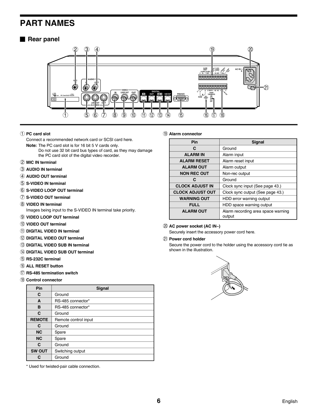
1PC card slot
Connect a recommended network card or SCSI card here. Note: The PC card slot is for 16 bit 5 V cards only.
Do not use 32 bit card bus types of card, as they may damage the PC card slot of the digital video recorder.
2MIC IN terminal
3AUDIO IN terminal
4AUDIO OUT terminal
5
6
7
8VIDEO IN terminal
Images being input to the
9VIDEO LOOP OUT terminal
FVIDEO OUT terminal
GDIGITAL VIDEO IN terminal
HDIGITAL VIDEO OUT terminal
IDIGITAL VIDEO SUB IN terminal
JDIGITAL VIDEO SUB OUT terminal
K
LALL RESET button
M
NControl connector
Pin | Signal |
C | Ground |
A | |
B | |
C | Ground |
REMOTE | Remote control input |
C | Ground |
NC | Spare |
NC | Spare |
C | Ground |
SW OUT | Switching output |
C | Ground |
|
|
* Used for
OAlarm connector
Pin | Signal |
C | Ground |
ALARM IN | Alarm input |
ALARM RESET | Alarm reset input |
ALARM OUT | Alarm output |
NON REC OUT | |
C | Ground |
CLOCK ADJUST IN | Clock sync input (See page 43.) |
CLOCK ADJUST OUT | Clock sync output (See page 43.) |
WARNING OUT | HDD error warning output |
FULL | HDD space warning output |
ALARM OUT | Alarm recording area space warning |
| output |
|
|
PAC power socket (AC IN~)
Securely insert the accessory power cord here.
QPower cord holder
Secure the power cord to the holder using the accessory cord tie as shown in the illustration.
6 | English |