CONNECTIONS
 Digital multiplexer connections
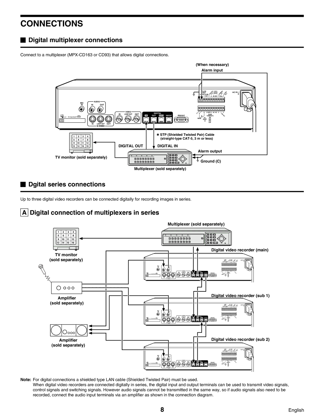
Connect to a multiplexer
(When necessary)
Alarm input
MIC
AUDIO
ALARM | NON OUT | CLOCK | WARNINGOUT ALARMFULL | ||
ALARM | ALARM | ADJUST | |||
RESET | REC |
| AC IN | ||
C IN | OUT | C | IN OUT | FULL | |
|
|
|
|
|
|
|
|
|
|
|
|
|
|
|
|
|
|
|
|
|
|
|
|
IN IN OUT
![]() EJECT PC Card SLOT
EJECT PC Card SLOT ![]()
IN LOOP OUT OUT
1 | 2 | 3 | 4 |
5 | 6 | 7 | 8 |
9 | 10 | 11 | 12 |
13 | 14 | 15 | 16 |
|
|
|
|
TV monitor (sold separately)
| VIDEO | DIGITAL |
| C A | B | C REMOTE C NC NC C | C |
IN | LOOP OUT OUT |
|
| RS485 | SW | ||
OUT SUB IN SUB OUT | RS232C |
|
| ||||
| IN |
|
| TERMINATE | OUT | ||
|
|
|
| RS485 | ALL | ON |
|
|
|
|
| RESET |
| ||
|
|
|
|
|
| ||
|
|
|
|
|
| OFF |
|
✱STP (Shielded Twisted Pair) Cable
DIGITAL OUT | DIGITAL IN |
Alarm output
![]() Ground (C)
Ground (C)
Multiplexer (sold separately)
 Dgital series connections
Up to three digital video recorders can be connected digitally for recording images in series.
A Digital connection of multiplexers in series
Multiplexer (sold separately)
1 | 2 | 3 | 4 |
|
|
|
5 | 6 | 7 | 8 |
|
|
|
9 | 10 | 11 | 12 |
|
|
|
13 | 14 | 15 | 16 |
|
|
|
TV monitor |
|
|
| |||
(sold separately) |
|
|
| |||
|
|
| MIC |
| AUDIO |
|
|
|
| IN |
| OUT |
|
|
|
| PC Card SLOT |
|
|
|
|
|
|
| IN | LOOP OUT | OUT |
|
|
|
|
|
| |
Amplifier |
|
|
| |||
(sold separately) |
|
|
| |||
|
|
| MIC |
| AUDIO |
|
|
|
| IN |
| OUT |
|
|
|
| PC Card SLOT |
|
|
|
|
|
|
| IN | LOOP OUT | OUT |
|
|
|
|
|
| |
Amplifier |
|
|
| |||
(sold separately) |
|
|
| |||
|
|
| MIC |
| AUDIO |
|
|
|
| IN | IN | OUT |
|
PC Card SLOT ![]()
IN LOOP OUT OUT
VIDEO
IN LOOP OUT OUT
VIDEO
IN LOOP OUT OUT
VIDEO
IN LOOP OUT OUT
Digital video recorder (main)
|
|
| ALARM |
| CLOCK | AC IN |
|
|
| RESET |
| ADJUST | |
|
| ALARM ALARM |
|
| ||
|
| C IN | OUT C | IN OUT | FULL | |
DIGITAL | C A | B | C REMOTE C | NC NC C | C | |
| RS485 |
| SW | |||
OUT | SUB IN SUB OUT | RS232C |
| TERMINATE | OUT | |
|
| RS485 | ALL | ON |
|
|
|
| RESET |
|
| ||
|
|
|
| OFF |
|
|
|
| Digital video recorder (sub 1) | ||||||
|
|
|
| ALARM |
| CLOCK |
| AC IN |
|
|
|
| RESET |
| ADJUST |
| |
|
|
| ALARM ALARM |
|
|
| ||
|
| C | IN | OUT C | IN OUT |
| FULL | |
| DIGITAL | C A |
| B | C REMOTE C | NC NC | C | C |
IN |
|
| RS485 |
|
| SW | ||
OUT SUB IN SUB OUT | RS232C |
|
| TERMINATE |
| OUT | ||
|
| RS485 | ALL | ON |
|
|
| |
|
| RESET |
|
|
| |||
|
|
|
|
| OFF |
|
|
|
|
| Digital video recorder (sub 2) | ||||||
|
|
|
| ALARM |
| CLOCK |
| AC IN |
|
|
|
| RESET |
| ADJUST |
| |
|
|
| ALARM ALARM |
|
|
| ||
|
| C | IN | OUT C | IN OUT |
| FULL | |
| DIGITAL | C A |
| B | C REMOTE C | NC NC | C | C |
|
|
| RS485 |
|
| SW | ||
| OUT SUB IN SUB OUT | RS232C |
|
| TERMINATE |
| OUT | |
|
| RS485 | ALL | ON |
|
|
| |
|
| RESET |
|
|
| |||
|
|
|
|
| OFF |
|
|
|
Note: For digital connections a shielded type LAN cable (Shielded Twisted Pair) must be used.
When digital video recorders are connected digitally in series, the digital input and output terminals can be used to transmit video signals, control signals and switching signals. However audio signals cannot be transmitted in the same way, so if audio signals also need to be recorded, connect the audio input terminals via an amplifier as shown in the connection diagram.
8 | English |