NETWORK SET SETTING
 NETWORK SET setting
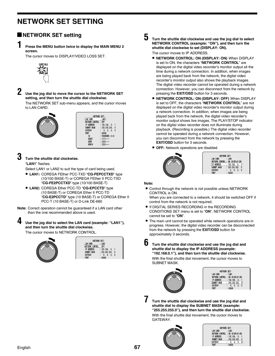
1 Press the MENU button twice to display the MAIN MENU 2 screen.
The cursor moves to DISPLAY/VIDEO LOSS SET.
MENU
5 Turn the shuttle dial clockwise and use the jog dial to select NETWORK CONTROL (example: “ ON” ), and then turn the shuttle dial clockwise to set (DISPLAY: ON).
The cursor moves to IP ADDRESS.
•
2 Use the jog dial to move the cursor to the NETWORK SET setting, and then turn the shuttle dial clockwise.
The NETWORK SET
<NETWORK SET> |
|
| ||
LAN CARD | : LAN1 |
|
|
|
NETWORK CONTROL | : OFF |
|
| |
IP ADDRESS | : 192.168. | 0. | 1 | |
SUBNET MASK | : 255.255.255. | 0 | ||
GATEWAY | : 0. 0. | 0. | 0 | |
PORT | : 00080 |
|
| |
ID | : PASSWORD |
| ||
GUEST | : |
|
| |
USER | : |
|
| |
ADMIN | : |
|
| |
3 Turn the shuttle dial clockwise.
“LAN1” flashes.
Select LAN1 or LAN2 to suit the type of card being used.
•LAN1: COREGA FEther
•LAN2: COREGA Ether
(10
Note: Correct operation cannot be guaranteed if a LAN card other than the one recommended above is used.
4 Use the jog dial to select the LAN card (example: “ LAN1” ), and then turn the shuttle dial clockwise.
The cursor moves to NETWORK CONTROL.
<NETWORK SET> |
|
|
| ||
LAN CARD | : LAN1 |
|
|
| |
NETWORK CONTROL | : OFF |
|
|
|
|
IP ADDRESS | : 192.168. | 0. | 1 | ||
SUBNET MASK | : 255.255.255. | 0 | |||
GATEWAY | : 0. | 0. | 0. | 0 | |
PORT | : 00080 |
|
| ||
•NETWORK CONTROL: ON (DISPLAY: OFF) When DISPLAY is set to OFF, the characters “NETWORK CONTROL” are not displayed on the digital video recorder’s monitor output during a network connection. In addition, when images are being played back from the network, the digital video recorder’s monitor output shows live images. The PLAY/STOP indicator on the digital video recorder does not illuminate during playback. (Recording is possible.) The digital video recorder cannot be operated during a network connection. However, you can disconnect from the network by pressing the EXIT/OSD button for 3 seconds.
•OFF: Network operations are disabled.
<NETWORK SET> |
|
|
| |
LAN CARD | : LAN1 |
|
|
|
NETWORK CONTROL | : ON (DISPLAY:ON) | |||
IP ADDRESS | : 192.168. | 0. | 1 | |
SUBNET MASK | : 255.255.255. | 0 | ||
GATEWAY | : 0. | 0. | 0. | 0 |
PORT | : 00080 |
|
|
|
Note:
•Control through the network is not possible unless NETWORK CONTROL is ON.
When you are connected to a network, it should be switched OFF if control from the network is not required.
•If DIGITAL SERIES RECORDING in the RECORDING CONDITIONS SET menu is set to “ON”, NETWORK CONTROL cannot be set to “ON”.
•The main unit cannot be operated while network operations are in progress. However, the digital video recorder can be disconnected from the network by pressing the EXIT/OSD button for approximately 3 seconds.
6 Turn the shuttle dial clockwise and use the jog dial and shuttle dial to display the IP ADDRESS (example:
“ 192.168.0.1” ), and then turn the shuttle dial clockwise.
With the final shuttle dial movement, the cursor moves to
SUBNET MASK.
<NETWORK SET> |
|
|
| |
LAN CARD | : LAN1 |
|
|
|
NETWORK CONTROL | : ON (DISPLAY:ON) | |||
IP ADDRESS | : 192.168. | 0. | 1 | |
SUBNET MASK | : 255.255.255. | 0 | ||
GATEWAY | : 0. | 0. | 0. | 0 |
PORT | : 00080 |
|
|
|
7 Turn the shuttle dial clockwise and use the jog dial and shuttle dial to display the SUBNET MASK (example:
“ 255.255.255.0” ), and then turn the shuttle dial clockwise.
With the final shuttle dial movement, the cursor moves to
GATEWAY.
English | 67 |
<NETWORK SET> |
|
|
| |
LAN CARD | : LAN1 |
|
|
|
NETWORK CONTROL | : ON (DISPLAY:ON) | |||
IP ADDRESS | : 192.168. | 0. | 1 | |
SUBNET MASK | : 255.255.255. | 0 | ||
GATEWAY | : 0. | 0. | 0. | 0 |
PORT | : 00080 |
|
|
|